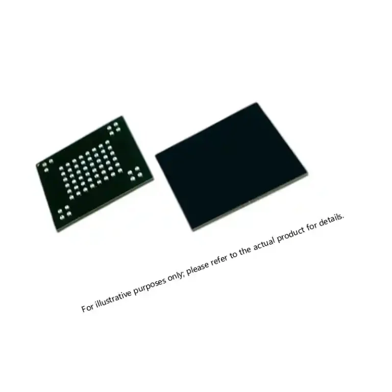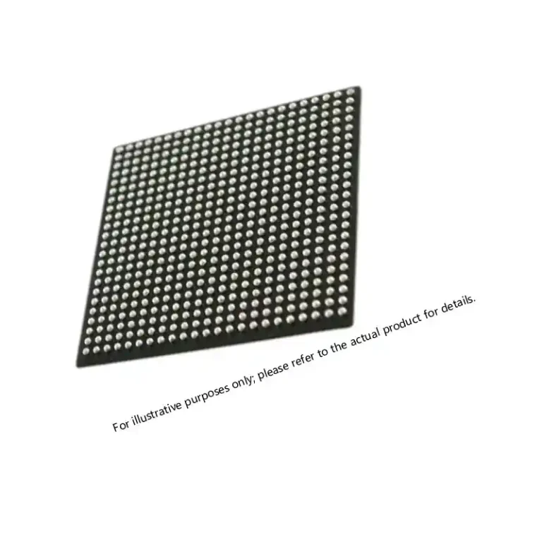

Military Inertial Navigation ICs for Defense Systems
Table of Contents
- Component Chain Behind Military Inertial Navigation ICs
- Analog and ADC/DAC Requirements for INS Signal Chains
- Which ADC parameters matter most for INS digitization?
- How do INS programs handle mixed signal and digital conversion?
- Processing, Memory, and FPGA Choices for Navigation Computers
- What role do FPGAs play in inertial sensor fusion?
- How does memory selection change over a long INS program?
- Environmental Qualification and Traceability for INS Components
- What does QML Class Q mean for INS components?
- Sourcing Hi-Rel INS Components Without Program Delays
- Questions Defense Buyers Ask About INS Components
- Does every military inertial navigation IC need QML qualification?
- How far in advance should we reserve inertial navigation ICs?
- Why do some legacy INS parts cost far more than similar commercial devices?
- What is the most common sourcing mistake on military inertial navigation IC projects?
Military inertial navigation ICs sit at the center of a navigation chain where a tiny bias drift or a missing screening record can become a qualification failure. The buyers who get INS programs through production look past the datasheet and weigh analog signal integrity, converter dynamic range, processing headroom, environmental qualification, and long-term supply continuity together. In my twelve years sourcing defense electronics, I have watched programs stall because a single line item had no traceable test history. For long-duration guidance and navigation work, the component decision is a documentation and continuity decision as much as a performance decision. The parts that meet mission profiles are verified, lot-controlled, and sourced with an audit trail.
Component Chain Behind Military Inertial Navigation ICs
An inertial navigation system is a signal chain, not a single chip. Gyroscopes and accelerometers produce small differential signals that need precision amplification before conversion. The converters then feed a processor or FPGA that runs alignment, filter, and sensor fusion algorithms. Interface devices move corrected position and attitude data to the flight control computer. Each stage has its own failure signature, and each stage has its own documentation burden. In the programs we work with, the first thing I check is not whether the converter is fast enough, but whether the lot can be traced to its burn-in report and certificate of conformance.
| Chain stage | Representative device types | What I evaluate first |
|---|---|---|
| Sensor conditioning | Low noise amplifiers, instrumentation amplifiers, voltage references | Offset drift, noise density, long-term stability |
| Digitization | High speed ADCs and DACs | Signal-to-noise ratio, jitter, interface compatibility |
| Processing | FPGAs, DSPs, military MCUs | Temperature rating, logic density, lifecycle status |
| Interface | MIL-STD-1553 transceivers, RS-422 transceivers | Protocol compliance, supply voltage range |
Analog and ADC/DAC Requirements for INS Signal Chains
The analog front end determines whether the navigation loop can separate a real motion signal from offset drift. A gyroscope output is not a clean digital value. It arrives as a low-level voltage riding on common-mode noise, and it has to be conditioned before it can be digitized. Precision amplifiers with low offset drift and high common-mode rejection are the difference between a stable heading and a drift that accumulates over minutes. For military inertial navigation ICs, we evaluate these parts on datasheet limits that still hold after temperature cycling, not on room-temperature typicals.
Which ADC parameters matter most for INS digitization?
Alias-free dynamic range matters more than raw sample rate. Inertial sensors often change by millivolts while the board environment moves by whole volts, so a converter with high resolution but poor noise density can bury the exact signal the loop needs. I look at signal-to-noise ratio, clock jitter, input bandwidth, and output interface together. Many older avionics boards still require LVDS or parallel outputs, and the wrong interface choice forces a board spin. Newer direct sampling converters include RF inputs and JESD204B interfaces, but they still have to fit the existing timing architecture.
How do INS programs handle mixed signal and digital conversion?
Most designs keep the conditioning and converter stages separate so that each can be qualified independently. That separation also makes it easier to replace one stage when a part goes end of life. In navigation work, mixed signal boards often carry a precision DAC alongside the ADC, for calibration and test signal injection. We see 16-bit and higher resolution converters used where the loop must resolve small changes, while high-speed RF sampling ADCs appear in software-defined navigation receivers.
Processing, Memory, and FPGA Choices for Navigation Computers
The navigation computer inside an INS is usually a split architecture. A hard real time processor handles built-in test and host communication, while an FPGA performs low-latency sampling, alignment math, and interface bridging. For military inertial navigation ICs in this stage, the selection logic is not raw logic density. It is radiation tolerance, temperature range, and whether the device will still be available in eight years. We have seen programs standardize on nonvolatile Actel FPGA families, including Axcelerator, ProASIC3E, and SmartFusion2 devices, for their configuration behavior and smaller power footprint.
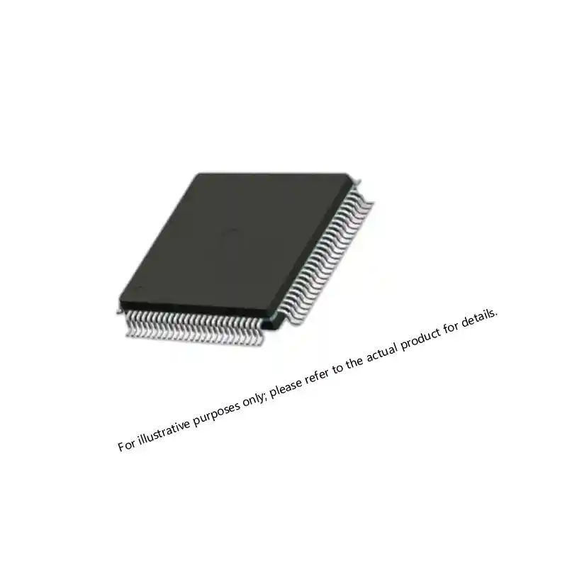
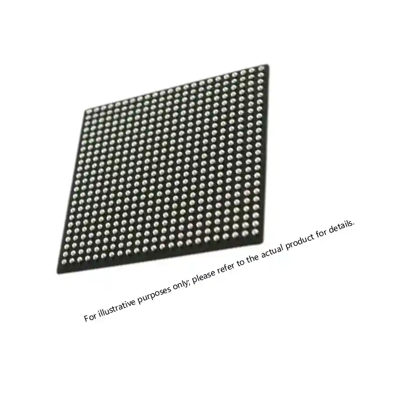
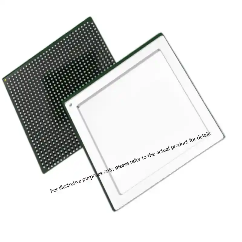
Memory choice follows the same logic. Nonvolatile SRAM holds calibration constants and alignment data that must survive power cycles. Boot flash and configuration memory need a documented programming path. If a program is intended to run for fifteen years, die banking and last time buy planning become part of the component decision, not an afterthought.
What role do FPGAs play in inertial sensor fusion?
An FPGA samples the ADC channels on a fixed clock, applies decimation and finite impulse response filters, and passes the conditioned data to the processor. That parallel, deterministic path is difficult to match with a processor alone. The FPGA also absorbs interface mismatches across legacy boards, which is why many INS programs keep an FPGA in the design even when the processor could handle the math.
How does memory selection change over a long INS program?
The initial build rarely controls memory cost. The real problem appears in year six, when a specialty SRAM or configuration device is no longer manufactured in a qualified flow. We ask for die and wafer documentation early, and we prefer devices with a documented alternate package or a second qualified source. That early check protects the program when the original line disappears.
Environmental Qualification and Traceability for INS Components
Military inertial navigation ICs do not become mission capable from a laboratory demonstration. The parts have to pass screening, burn-in, and environmental testing that matches the platform. For monolithic devices, QML Class Q under MIL-PRF-38535 carries electrical test data, temperature cycling, constant acceleration, and particle impact noise detection records. For discretes, JANTX and JANTXV levels define reliability tiers that matter when a guidance unit cannot be swapped easily in the field. We treat any certificate of conformance as incomplete if it does not identify the original manufacturer, the test lot, and the screening flow used.
If your INS program mixes legacy navigation parts with newer signal processing upgrades, it is worth confirming the screening documentation and alternate sourcing path before you freeze the bill of materials. Send the part numbers to xuansc2144@gmail.com and we will confirm what documentation is available.
What does QML Class Q mean for INS components?
QML Class Q is a monolithic device class under MIL-PRF-38535, not a general quality label. It means the manufacturer follows a qualified manufacturing line with documented screening and quality conformance inspection. A Class Q device should arrive with lot-specific test data that lets a buyer trace the part back to its wafer fabrication and assembly flow. For INS programs, that traceability matters because a field failure in a navigation unit can ground a platform and trigger a full lot review.
Sourcing Hi-Rel INS Components Without Program Delays
The most expensive sourcing mistake on an INS program is discovering at prototype build that a critical part has a 40-week lead time and no second source. We work backwards from the program schedule. For long-lead devices, we confirm allocation and delivery positions before the design review closes. For hard-to-find legacy parts, we check recent lot dates, original packaging, and test documentation before quoting anything. A low price on an open market part with no traceable history is usually a future qualification problem.
The practical route for military inertial navigation ICs is to keep a verified shortlist of suppliers who can deliver both new allocations and legacy discontinued parts with documentation. At Sparkle Electronics, we maintain stock across FPGA, DSP, high-speed ADC and DAC, memory, power, and interface categories used in navigation and guidance systems. Send your part number, quantity, and required date to xuansc2144@gmail.com. We will confirm current availability, traceability, and screening documentation before you commit.
Questions Defense Buyers Ask About INS Components
Does every military inertial navigation IC need QML qualification?
No. QML qualification applies to monolithic devices covered by MIL-PRF-38535, while discrete semiconductors may be procured under JANTX or JANTXV certification. Some passive or support devices can enter a program as tested commercial parts if the program up-screens them and documents the process. The binding requirement is that the component class matches the documentation set. A QML Grade derived part cannot be substituted for QML Class Q without a formal qualification decision.
How far in advance should we reserve inertial navigation ICs?
It depends on the device class and whether a die bank already exists. QML, radiation tolerant, and rad hard parts often run 26 to 52 weeks or longer when allocation is tight. Commercial up-screened parts can move faster if the wafer lot is already in distribution. I recommend locking vendor schedules at design review, then confirming delivery positions again at critical design review and production readiness review.
Why do some legacy INS parts cost far more than similar commercial devices?
The price rarely comes from the silicon. Legacy navigation parts carry qualification overhead, low-volume packaging, and the cost of maintaining a discontinued process. Buyers are paying to keep a documented source alive for a platform that may only need a few hundred pieces a year. The alternative is redesign, which costs far more than the unit price difference.
What is the most common sourcing mistake on military inertial navigation IC projects?
In the programs we have worked on, the most common mistake is freezing the bill of materials before checking second-source and screening documentation. Design teams select the part, and procurement later discovers the only available source is an unauthorized broker list. Before you freeze the BOM, confirm that every line item has traceable test history and a defined alternate path for long-lead devices. If your INS program is entering qualification, share your part numbers and we will confirm which screening documents stay with each component through delivery at xuansc2144@gmail.com.
If you’re interested, check out these related articles:
Virtex-7 XC7VX690T: Performance, Reliability, and Integration
UltraScale KU085 FPGA Specifications for Defense Systems