
CA91C142D-33IB VMEbus-PCI Bridge: 33 MHz Specs and Sourcing Guide
Table of Contents
- Functional Role and Key Specifications
- Integration Architecture in VME Systems
- Legacy Program Risks: Counterfeit, Traceability, and Obsolescence
- Sourcing and Long-Term Program Support
- End CTA
- Frequently Asked Questions
- What does the 33IB suffix indicate in CA91C142D-33IB?
- Can CA91C142D-33IB support 64-bit VMEbus transfers?
- What documentation should accompany a defense or avionics purchase?
- Is the CA91C142D-33IB still in production?
- What companion components are commonly needed for a VMEbus bridge design?
- References
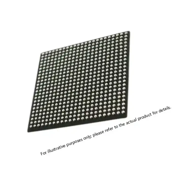
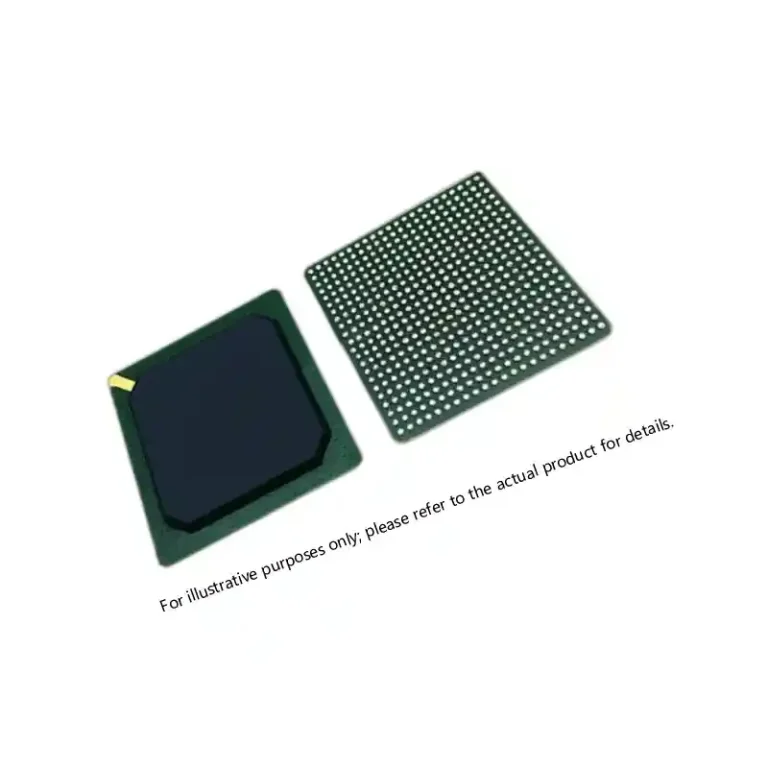
The CA91C142D-33IB is a VMEbus-to-PCI bridge built around the Tundra Universe II architecture. It gives modern PCI host processors a controlled path into VMEbus address space while letting installed VMEbus boards access host memory and resources. For defense, avionics, and industrial programs that must keep legacy VMEbus line-replaceable units alive, this device is often the difference between a clean technology-refresh path and an expensive board redesign. This guide covers the bridge’s functional role, key electrical and bus-level specifications, integration considerations, and sourcing controls for program-ready use.
Functional Role and Key Specifications
The CA91C142D-33IB functions as a bus interface between a PCI local bus and a VMEbus backplane. The -33 designation identifies the PCI clock grade for the device, and the IB suffix is the factory package and lead-configuration identifier. The bridge appears in systems where a processor board uses PCI internally but must communicate with installed VMEbus boards, and in VME boards that need direct access to host-side memory and interrupts.
On the VMEbus side, the part supports the VME64 features defined in VITA 1.0, including 64-bit data movement and multiplexed block transfer; the VME64 specification provides a theoretical maximum of 80 MB/s under 64-bit block-transfer conditions [1]. This allows the bridge to connect PCI-based compute engines to the large installed base of VMEbus boards without forcing every card in the chassis to be replaced at once. The VMEbus interface builds on the baseline defined in IEEE 1014, which established the original VMEbus backplane, signal, and timing framework [2].
The PCI interface follows the 33 MHz operation defined in PCI Local Bus Specification Revision 2.1 [5]. In practice, the bus width and configuration require review of the original device datasheet, because board-level implementation details such as address windows, byte swapping, and interrupt routing are controlled through the bridge’s configuration registers. The bridge provides address translation, DMA support, and FIFO buffering so that VMEbus and PCI bus timing do not have to be aligned cycle-for-cycle.
No article should replace the original datasheet for pinout, register, or electrical verification. The CA91C142D-33IB is a register-rich bridge device, and errors in initialization can produce subtle bus faults that are difficult to isolate after deployment.
Integration Architecture in VME Systems
In a typical VMEbus chassis, the bridge sits between the host processor’s PCI bus and the VMEbus backplane. The most common integration tasks are configuring address windows, mapping VMEbus address regions into PCI memory space, setting up byte-swap control, and assigning interrupt levels. Because VMEbus and PCI use different byte ordering conventions, the bridge performs the necessary conversion, but the design team must still verify that the address mapping matches the software’s view of each VMEbus board.
VMEbus systems that use 64-bit block transfers can move large amounts of data during backplane reads and writes, but the effective throughput depends on the slot population, backplane quality, bus grants, and the number of active bus masters [1]. For deterministic acquisition and signal-processing platforms, designers typically isolate the bridge behind a dedicated address region and avoid mixing large DMA streams with frequent configuration traffic.
The package and thermal profile are important in legacy card guides. The IB package requires confirmation against the factory procurement drawing before footprint layout, because package variants across CA91C142D versions are not always interchangeable. A thermally aggressive chassis that was designed for an older bridge should be rechecked when a replacement board uses a different package or power profile, particularly if the board is being requalified for airborne or sealed-enclosure use.
Legacy Program Risks: Counterfeit, Traceability, and Obsolescence
The CA91C142D-33IB is a mature device, which makes it vulnerable to gray-market and counterfeit substitution. Defense programs should treat every lot as a controlled acquisition rather than a commodity purchase. SAE AS5553B provides the counterfeit-avoidance framework now expected in many aerospace and defense supply chains, including supplier assessment, verification testing, and disposition controls for suspect parts [4]. The risk is not theoretical: bridge devices from mixed sources can carry overwritten date codes, recycled packaging, or incorrect die revisions that fail silently in operational firmware.
Incoming inspection should verify the physical marking, package condition, date and lot codes, and electrical continuity against the documented source. When hi-rel screening is required, test sequences are typically aligned to MIL-STD-883 as the general test-method framework for microcircuits, with the specific methods and conditions selected for the program’s quality level [3]. That screening may include external visual inspection, electrical parameter tests, and burn-in or temperature cycling when the program requires it.
For obsolescence management, the useful path is to combine last-time-buy inventory, board-level substitutions, and long-term storage controls. A procurement team should never accept “same function, same footprint” without verifying register compatibility, because bridge parts can differ in initialization sequences even when the package appears identical.
If you are qualifying a replacement CA91C142D-33IB or building a bridge supply across multiple production lots, send the full part number, lot code, and required quality clauses to xuansc2144@gmail.com for a compliance-first quotation and documentation review.
Sourcing and Long-Term Program Support
A program-grade CA91C142D-33IB purchase should include more than a parts list. Request the manufacturer part number, date and lot codes, quantity, and the available documentation chain: Certificate of Conformance, traceability records, and any screening or test data tied to the lot. For defense and avionics programs, the supplier should be able to explain the chain of custody and confirm that the parts were not sourced from uncontrolled broker stock [4].
Board-level sustainment also requires the surrounding components to be planned together. VMEbus backplanes in legacy systems often pair the bridge with an antifuse or flash-based FPGA for address decode, watchdogs, protocol adaptation, and secondary bus control. When an FPGA companion is also going EOL, the full bill of materials needs a coordinated last-time-buy or drop-in replacement strategy.
VMEbus backplanes in legacy defense systems frequently pair a bridge device with an antifuse or flash-based FPGA for address decode, watchdogs, and protocol adaptation. <A1020B-PG84B ACT2 FPGA: Specs, Sourcing, and Availability> covers legacy ACT2 sourcing, package availability, and long-life bus-interface design.
Sparkle Electronics supports CA91C142D-33IB sourcing through controlled lot review, incoming verification, and long-term program support. For a documented quote, email xuansc2144@gmail.com with your quantity, target delivery date, and required certification or screening level.
Modern VMEbus single-board computers often route high-bandwidth sensor data through an FPGA before the data crosses the PCI-to-VMEbus boundary. <XC7VX485T FPGA: Virtex-7 Performance for Defense> covers Virtex-7 performance, signal-processing density, and defense-oriented sourcing.
For mission-critical VME systems moving to higher-throughput processing cards, bridge selection and FPGA bandwidth planning must be evaluated together. <XCKU115 UltraScale FPGA: Powering Critical Defense Systems> covers UltraScale FPGA integration, power, and reliability in critical defense systems.
The same control discipline also applies to the surrounding logic inventory:
End CTA
Sparkle Electronics provides traceable, compliance-focused sourcing for military-grade and high-reliability components, including mature VMEbus bridge devices and their companion logic. Send your BOM, required certifications, and target schedule to xuansc2144@gmail.com for a documented RFQ response and program-support review.
Frequently Asked Questions
What does the 33IB suffix indicate in CA91C142D-33IB?
The 33 identifies the PCI clock grade, and IB identifies the factory package and lead-configuration variant. Confirm the exact package dimensions, ball assignment, and power requirements against the original datasheet before layout or replacement.
Can CA91C142D-33IB support 64-bit VMEbus transfers?
The device supports the VME64 feature set, including 64-bit multiplexed block transfer, when configured and mated to a compliant VME64 backplane [1]. Actual use depends on the board design, backplane, and software setup.
What documentation should accompany a defense or avionics purchase?
At minimum, request a Certificate of Conformance, date and lot codes, traceability records, and any screening or electrical test data. Programs using AS5553B-based counterfeit controls should also require supplier risk disclosure for the specific lot [4].
Is the CA91C142D-33IB still in production?
Lifecycle status varies across qualified sources and package variants. Programs should confirm current production or last-time-buy status with an authorized or controlled distributor, then secure inventory with documented storage and lot-control procedures.
What companion components are commonly needed for a VMEbus bridge design?
Typical companion parts include termination networks, bus transceivers where required, configuration or address-decode logic, and FPGA or CPLD devices for board-level control. Obsolescence planning should address the full bridge-to-backplane BOM rather than the bridge alone.
References
[1] ANSI/VITA 1.0-1994, VME64 Standard, VMEbus International Trade Association. https://www.vita.com/vme64
[2] IEEE Std 1014-1987, IEEE Standard for a Versatile Backplane Bus: VMEbus. https://standards.ieee.org/ieee/1014/1030/
[3] U.S. Department of Defense, MIL-STD-883K, Test Method Standard for Microcircuits, 2018. https://quicksearch.dla.mil/qsDocDetails.aspx?ident_number=35924
[4] SAE AS5553B, Counterfeit Electrical, Electronic, and Electromechanical Parts: Avoidance, Detection, Mitigation, and Disposition, SAE International. https://www.sae.org/standards/content/as5553b/
[5] PCI-SIG, PCI Local Bus Specification, Revision 2.1, 1995. https://pcisig.com
If you’re interested, check out these related articles:
Virtex-7 690T FPGA: Performance for Mission-Critical Systems
Virtex-7 XC7VX690T: Performance and Reliability Insights
XCKU085 UltraScale FPGA: Performance for Critical Systems
XC7VX485T Virtex-7 FPGA: Performance and Sourcing for Defense