
Choosing Electronic Components for Military EO/IR Systems
Table of Contents
- Detector Interface and Readout Components for EO/IR Systems
- High-Speed ADCs and DACs in EO/IR Signal Chains
- What ADC Sample Rate Fits Staring and Scanning EO/IR Arrays?
- FPGA and DSP Processing Subsystems
- Why Flash-Based FPGAs Matter in Gimbal and Pod Electronics
- Power and Thermal Management for EO/IR Electronics
- Why Power Rail Noise Shows Up in the Image
- Procurement and Traceability Requirements for Military EO/IR Components
- Common Questions About Military EO/IR Component Sourcing
- What Makes a Component Suitable for a Military EO/IR System?
- Is Radiation Hardening Required for Ground EO/IR Platforms?
- How Do Long Lead Times Change EO/IR Component Planning?
- Can Commercial Components Be Used in Prototype EO/IR Systems?
Military electro-optical and infrared (EO/IR) systems convert photons into decisions. The electronics behind the detector set range, resolution, false alarm rate, and the power bill for the whole platform. Choosing electronic components for military EO/IR systems means designing for wide-temperature swings, vibration, long lead times, and traceability from wafer lot to system. The signal chain runs from a cooled detector interface through a high-speed analog front end, data converters, FPGA or DSP processing, and tightly regulated power. The FPGA choice in particular should follow the detector interface and cooling budget, not raw gate count.
Detector Interface and Readout Components for EO/IR Systems
For cooled mid-wave and long-wave infrared arrays, the readout integrated circuit sits inside the dewar next to the detector. It performs charge integration, correlated double sampling, and multiplexing. Outside the dewar, low-noise preamplifiers and clock drivers handle the analog output. The parts that people forget are usually the precision voltage references and the clock distribution. Low-frequency noise in either one shows up as fixed pattern noise or a shifting bias point.
| Subsystem | Representative Components | Key Selection Drivers |
|---|---|---|
| Detector interface | ROIC, low-noise op amps, LVDS receivers, precision references | Noise density, timing skew, dewar thermal load |
| Analog front end | Differential amplifiers, variable gain amplifiers | Dynamic range, common-mode rejection |
| Data conversion | High-speed ADCs and DACs | Sample rate, jitter, output interface |
| Processing | FPGAs and DSPs | Logic density, DSP slices, I/O count |
| Power | DC-DC modules and LDOs | Ripple, load transient, cold start |
One early decision is whether the ROIC outputs serial LVDS or a single-ended CCD-style signal. That choice cascades into cable length, connector pin count, and the analog front end. We have seen ROIC timing failures on cooled mid-wave arrays when a commercial clock buffer was substituted for a military-temperature part. The replacement worked on the bench but failed during a fast cooldown because the timing skew doubled at the low end of the temperature range.
High-Speed ADCs and DACs in EO/IR Signal Chains
Above a few megapixels per second, the ADC becomes the gatekeeper for range and resolution. A mid-wave system with 640 by 512 pixels at 120 Hz produces about 39 megapixels per second. Pushing that through two or four output taps means each converter runs between 80 and 250 MSPS. High-speed parts such as the ADC12D1600, AD9680, and DAC38RF82 appear often in these designs. The DAC side matters for laser rangefinders and countermeasure test benches, where arbitrary waveform generation tests the receiver path before the sensor goes into the pod.
What ADC Sample Rate Fits Staring and Scanning EO/IR Arrays?
A 640 by 512 mid-wave array at 120 Hz produces about 39 megapixels per second. A 14-bit digitizer running at 80 MSPS can handle two multiplexed outputs, while a 320 by 256 long-wave array with slower frame rates needs far less. Scanning systems with time delay integration often demand 1 GSPS converters because multiple detector channels are multiplexed before digitization. The sample rate matters less than the jitter. At 1 GSPS, 500 femtoseconds of clock jitter can turn a 16-bit ambition into a 10-bit result.
FPGA and DSP Processing Subsystems
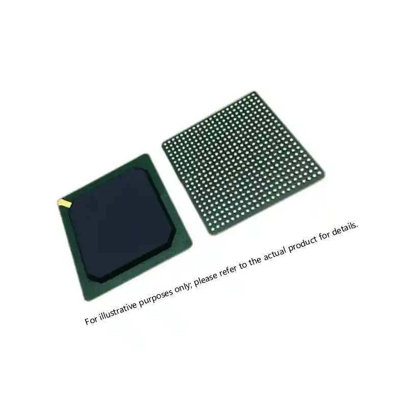
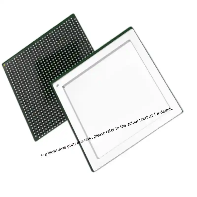
Once the data leaves the converter, the FPGA or DSP has to co-register channels, apply non-uniformity correction, and run detection filters without adding frame latency. In a narrow field of view tracker, latency below one frame can be the difference between keeping a target in track and losing it. FPGAs from Microsemi and Xilinx occupy most of the designs we encounter. Flash-based parts such as the ProASIC3, SmartFusion2, and PolarFire fit well in sealed gimbals where power and configuration simplicity outweigh raw throughput.
Why Flash-Based FPGAs Matter in Gimbal and Pod Electronics
Gimbal electronics rarely have the space for a large configuration flash, and every startup sequence matters on a mission. Flash-based FPGAs boot instantly and draw less inrush current. That reduces power supply sequencing complexity. We have seen SRAM-based devices require external configuration memory and a larger reset supervisor, which adds failure points inside a sealed pod. For image processing, Kintex-7 or Virtex-5 devices still win on raw DSP throughput, but only when the power budget and heatsinking can tolerate them.
If your EO/IR program uses a fast slew gimbal or long-range detection beyond 12 km, the ADC jitter and FPGA latency tradeoff is worth confirming before the bill of materials is frozen. Send your block diagram or part list to xuansc2144@gmail.com to confirm compatibility and current stock.
Power and Thermal Management for EO/IR Electronics
Power design decides whether the sensor survives cold start and how much thermal margin the dewar cooler actually gets. The cryocooler draws a sudden current spike at startup, and the entire analog chain shares a board with digital switching noise. Military-grade DC-DC converters and low-dropout regulators are the standard approach. A VICOR V300A28H500BN or similar wide-input converter handles the bus, followed by separate low-noise LDOs for the analog and digital rails. We have seen boards that met ripple spec at room temperature fail during a -40°C cold start because the compensation network was set for a narrow industrial range.
Why Power Rail Noise Shows Up in the Image
Noise on the analog supply appears as horizontal streaks or fixed pattern artifacts because the ROIC and ADC share the same reference. A 5 mV ripple on a 1 V reference can shift the least significant bits before the image processor sees data. We have measured boards where a commercial LDO met the static ripple spec but oscillated under load transient from the cryocooler. The fix was a military-grade converter with a dedicated low-noise LDO for the analog rail and a separate digital rail for the FPGA.
Procurement and Traceability Requirements for Military EO/IR Components
The sourcing half of the problem is documentation. A part can be electrically correct and still be unusable if the chain of custody stops at a broker. Every component for a military EO/IR system should arrive with documentation that links the order to the original wafer lot, test reports, and a certificate of conformance. QML, 5962-series, JANTX, and JANTXV markings show that the device was screened to MIL-PRF-38535 or the equivalent discrete specification. For long-running programs, that paperwork matters as much as the silicon.
The pain point for most teams is not finding a part number, it is confirming that the part you receive is the same lot you qualified. Sparkle Electronics holds inventory across FPGA, DSP, high-speed ADC/DAC, analog signal chain, memory, and MIL-SPEC passives and connectors for EO/IR programs. Send your part number and required quantity to xuansc2144@gmail.com and we will confirm traceability, compliance, and lead time before you commit the bill of materials.
Common Questions About Military EO/IR Component Sourcing
What Makes a Component Suitable for a Military EO/IR System?
A suitable component must hold its electrical repeatability across the full -45°C to +85°C or -55°C to +125°C environment while surviving vibration and shock. The data sheet tells only part of the story. We look for MIL-PRF-38535, 5962-series, JANTX/JANTXV, or QML device types, plus lot-level test documentation that links the part to one wafer run. Hermetic ceramic packages beat plastic in high-humidity and salt fog exposure. Low-frequency noise in op amps and voltage references matters more than headline bandwidth because it appears directly as fixed pattern noise in the image.
Is Radiation Hardening Required for Ground EO/IR Platforms?
Radiation hardening is often assumed to be mandatory, but most ground vehicle and naval EO/IR systems do not need space-grade total ionizing dose ratings. The real requirement is latchup immunity and single-event upset tolerance at the altitude and latitude where the platform operates. For pods flying above 30,000 feet, radiation-tolerant FPGAs and hardened power controllers make sense. For a vehicle-mounted sight used below 10,000 feet, standard military-temperature logic is often sufficient if the power sequencing and watchdog design are sound.
How Do Long Lead Times Change EO/IR Component Planning?
Long lead times affect different parts differently, and it depends on whether the part is a high-volume commercial die that can be screened or a QML device with a fixed production window. For microprocessors and advanced FPGAs, we usually plan 30 to 52 weeks when there is no existing stock. For MIL-SPEC passives and mature 1553 transceivers, stock can often be confirmed within days. If a program cannot absorb a 26-week gap, the safer path is to qualify a second source or reserve buffer inventory before design freeze.
Can Commercial Components Be Used in Prototype EO/IR Systems?
In prototype builds we have worked on, commercial parts can shorten first integration by weeks because they are stocked and inexpensive. The condition is that the bill of materials must flag every commercial item for replacement before qualification testing. We have also seen prototypes pass functional checks with commercial DC-DC converters and then fail during thermal vacuum because the modules behaved differently at cold start. If your prototype still needs MIL-SPEC parts before qualification, send the part list and quantities to xuansc2144@gmail.com and we will confirm stock and documentation before you place the order.
If you’re interested, check out these related articles:
Virtex-7 XC7VX690T: Performance and Reliability Insights
Virtex-7 XC7VX690T: Performance, Reliability, and Integration
Virtex-7 690T FPGA: Performance for Mission-Critical Systems