Military Electronics Vibration and Shock: What to Specify
Table of Contents
- Military Electronics Vibration and Shock Begins With Platform Data
- The Test Method Is Not the Same as an Acceptance Limit
- Board-Level Response Defines More Than the Component Datasheet
- A Shock Requirement Without a Peak Value Is Not a Requirement
- Specifying Military Electronics Vibration and Shock for a Program You Can Source
- Common Questions About Military Electronics Vibration and Shock
- What is the difference between sinusoidal and random vibration?
- Do shock ratings replace vibration ratings?
- Which MIL-SPEC test method applies to avionics vibration?
- What should a component distributor know about vibration specifications?
Military Electronics Vibration and Shock requirements fail most often before a part is ever mounted. In twelve years of sourcing MIL-SPEC components, I have seen more rejections trace back to an incomplete vibration profile than to a weak component. If you call out a test method without profiling the platform, the board, and the mounting interface, you are not specifying reliability. You are transferring risk to the next design review. This article explains what to specify for vibration and shock resistance in military electronic components, and where the specification must go beyond the datasheet.
Military Electronics Vibration and Shock Begins With Platform Data
Most procurement teams start with a component datasheet and a test standard. That order is backwards. The vibration and shock environment comes from the platform first: a helicopter rotor head, a tracked vehicle hull, a missile canister, or an aircraft pylon. Each one produces a different frequency content, a different peak acceleration, and a different fatigue cycle count. Without that platform data, a MIL-SPEC part number tells you only that the device passed a generic qualification. It does not tell you whether the device will survive the specific mounting location.
The first two numbers I ask for are the power spectral density profile and the shock response spectrum. The power spectral density profile defines how much energy is present at each frequency during random vibration. The shock response spectrum defines the maximum response of a single-degree-of-freedom system to a transient shock pulse. If a program cannot produce either one, the specification is not ready for supplier review. I have seen teams spend weeks comparing part numbers while the platform shock level was still described as “severe, to be determined.” That is a procurement delay waiting to happen.
Platform data then determines the three specification layers: the component test standard, the board-level mechanical requirement, and the assembly-level verification. MIL-STD-810 Method 514.8 covers vibration testing and Method 516.8 covers shock testing, but neither standard sets the acceptance limits. The program must set those limits from the platform profile. A component supplier can only respond to what is written. If the written requirement is silent on frequency range, duration, axis count, and failure criteria, the quote will be fast but the risk will sit with the program office.
The Test Method Is Not the Same as an Acceptance Limit
Method 514.8 is often cited as if it were a complete vibration requirement. It is not. It describes a family of test procedures for sinusoidal vibration, random vibration, and gunfire vibration. Method 516.8 similarly describes functional, crash, and transit drop shock tests. Neither method states the g level, the duration, the number of axes, or the number of shocks. Those values come from the platform profile and the intended mission phase. A drawing that says “comply with MIL-STD-810G, Method 514.8” without these numbers is a starting point, not a specification.
| Requirement element | Vibration test content | Shock test content |
| Reference method | MIL-STD-810 Method 514.8 | MIL-STD-810 Method 516.8 |
| Common profile | Random vibration across 20 to 2000 Hz | Half-sine or terminal peak sawtooth pulse |
| Typical failure mode | Solder fatigue, lead fracture, connector fretting | Lead separation, ceramic cracking, substrate fracture |
| Incomplete spec trap | Stating g RMS without the PSD curve | Stating peak g without pulse width or axis count |
Two numbers illustrate the difference. A random vibration spec that lists 12 g RMS means little without the frequency range and the power spectral density shape. A low-frequency dominated profile can produce the same RMS value as a high-frequency dominated profile while driving completely different failure modes. The same problem appears in shock: a 75 g half-sine at 6 milliseconds is not the same load as a 75 g terminal peak sawtooth at 11 milliseconds. The pulse shape controls which failure mechanism dominates.
Board-Level Response Defines More Than the Component Datasheet
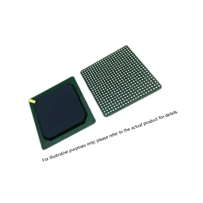
Once the platform profile is set, the next variable is the printed circuit board. Military electronic components do not see the platform vibration directly. They see the amplified response of the board at the board’s natural frequencies. A rigid enclosure and a MIL-SPEC BGA do not help if the board resonates at 180 Hz and the component is mounted at the antinode. Board stiffness, mounting standoff locations, component placement, and underfill all change the local acceleration at the package.
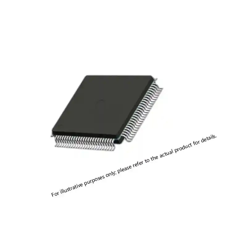
For ceramic components, the risk is concentrated at the board interface. Ceramic capacitors and chip resistors can crack when board flexure exceeds the manufacturer’s limit during shock or vibration. The failure is often intermittent, which makes it worse. A solder joint may crack partially and pass electrical test until the board cools or flexes again. The component level test may have passed, but the assembly level condition was never specified.
I have seen a switch from a leaded package to a QFN package fail qualification because the board was not re-evaluated for the new footprint. The QFN passed component-level vibration but cracked under board-level bending. The source control drawing had not been updated.
If your program involves a MIL-SPEC QML or 5962-series device and the platform profile is still in draft, it is worth confirming the shock axis definitions before finalizing the BOM. Send the part number and the current profile to xuansc2144@gmail.com and we can flag where the document will conflict with the component qualification.
A Shock Requirement Without a Peak Value Is Not a Requirement
A shock requirement needs four parameters at minimum: peak acceleration, pulse shape, pulse duration, and the number of shock pulses per axis. Some specifications add functional versus survival criteria, direction, and whether the unit is powered during the test. If any of the first four values is missing, the requirement cannot be reproduced. Two different labs will read the same line item differently.
Functional shock means the equipment must operate during and immediately after the shock event. Survival shock means the equipment may stop operating during the event but must return to normal after inspection or reset. Many missile and gun launch applications use survival shock because the component is non-operational during the firing event. But what matters for procurement is that the line item states which one applies. A supplier cannot quote the same part if the requirement is ambiguous.
I typically ask whether the unit is powered and processing data when the shock occurs. If yes, the spec must state the bit error rate or output deviation allowed during the event. If no, the spec should say so and define the post-shock acceptance test.
Specifying Military Electronics Vibration and Shock for a Program You Can Source
Many programs reach the RFQ stage with the right platform profile but leave the mechanical requirements scattered across three documents. The component drawing references a test method. The assembly drawing lists a board thickness. The qualification plan defines a different shock axis. The result is a quote that takes longer, because the distributor and the component manufacturer have to resolve the conflict before they can commit to a schedule.
If your program involves a MIL-SPEC, QML, JANTX, or 5962-series device and you are still finalizing mechanical requirements, send the part number, the platform profile, and the mounting details to xuansc2144@gmail.com. We confirm that the component screening and the assembly-level constraints line up before the BOM is released. A single message with the part number and quantity keeps the sourcing step from becoming the schedule risk.
Common Questions About Military Electronics Vibration and Shock
What is the difference between sinusoidal and random vibration?
Sinusoidal vibration applies a single frequency at a time, while random vibration applies a spectrum of frequencies simultaneously. Sinusoidal testing identifies resonances and is used during swept-sine qualification. Random testing better represents real-world operation because platforms such as tracked vehicles and helicopters excite many frequencies at once. For component procurement, random vibration is usually the more demanding specification because it accumulates fatigue across the full frequency band. If a drawing only lists a sine sweep, confirm whether the program also requires a random vibration profile before the BOM is finalized.
Do shock ratings replace vibration ratings?
No, shock ratings test a different failure mechanism and do not replace vibration ratings. Shock testing evaluates a single high-energy transient, while vibration testing evaluates fatigue damage over many cycles. A part can survive a 100 g shock pulse but fail after extended random vibration because solder accumulates microcracks. Military procurement should carry both requirements when the platform environment includes both conditions. The two tests are complementary, not interchangeable.
Which MIL-SPEC test method applies to avionics vibration?
It depends on the platform and the installation location. Fixed-wing aircraft often use MIL-STD-810 Method 514.8 with a random vibration profile derived from measured flight data, while rotorcraft use a different spectrum because of rotor-induced low-frequency energy. Some avionics programs also reference DO-160G sections for environmental testing. The key is to specify the test method and the platform-specific profile together. A bare method number does not define the component requirement.
What should a component distributor know about vibration specifications?
In programs our team has worked on, the distributor should know the platform profile, the mounting condition, and the shock axis definitions before the RFQ is released. That information affects part suitability, packaging, and sometimes screening options. Without it, the distributor can only quote the part number and the datasheet limits. If your team is preparing a mechanical specification for a MIL-SPEC or QML device, send the part number and the current profile to xuansc2144@gmail.com and we can confirm the drawing is ready for a clean source control review.
If you’re interested, check out these related articles:
UltraScale KU085 FPGA Specifications for Defense Systems
A1020B-PG84B ACT2 FPGA: Specs, Sourcing, and Availability