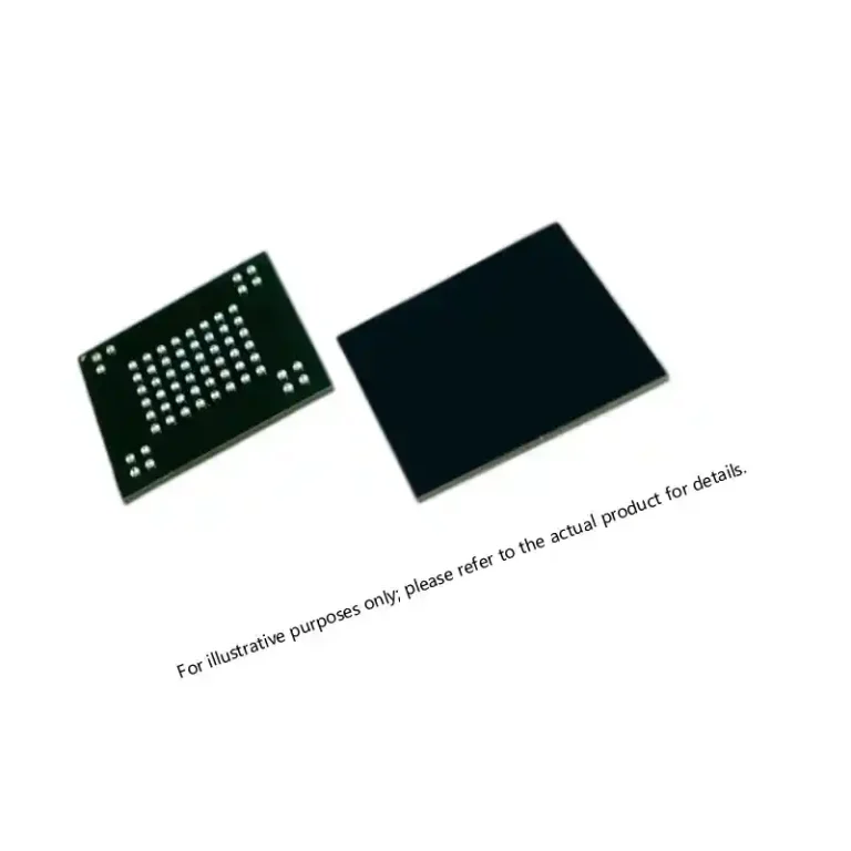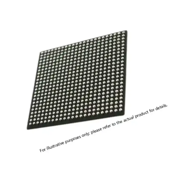

Space Electronics Components: Hi-Rel Parts for Payload and Bus Systems
Table of Contents
- Payload vs. Bus: Different Priorities, Shared Hi-Rel Baseline
- Radiation Environment: TID and Single-Event Effects
- Onboard Processing: FPGA and Configurable Logic
- Data Conversion and Signal Chain
- Memory, Configuration Storage, and Non-Volatile Logic
- Power Conversion and Distribution
- Qualification, Screening, and Lot-Level Confidence
- Traceability, Documentation, and Counterfeit Control
- Long-Life Program Support and Obsolescence
- Component Request Checklist for Space Programs
- Frequently Asked Questions
- What is the difference between payload and bus electronics?
- Are radiation-hardened components always required for space missions?
- What does QML Class V mean?
- How are commercial components upscreened for space use?
- What documentation should accompany each space-qualified lot?
- References
Payload and bus electronics for space programs operate inside a stress environment that does not appear in terrestrial equipment: cumulative total ionizing dose (TID), single-event effects from heavy ions and protons, wide thermal cycling, vacuum outgassing, and high-random-vibration launch loads. Each of these conditions drives component selection, screening, and derating before the first prototype is assembled [1][2].
The procurement challenge is that payload and bus subsystems do not demand the same component profiles. Payload electronics are often mission-specific and signal-intensive; bus electronics are more standardized but carry the entire spacecraft through every phase of the mission. A structured sourcing approach starts with separating these two domains, then applying a common high-reliability baseline to both.
Payload vs. Bus: Different Priorities, Shared Hi-Rel Baseline
Payload electronics generally include high-throughput processing, wideband data conversion, RF transceivers, and mission-specific sensor interfaces. Bus electronics cover command and data handling, power conditioning and distribution, attitude control, telemetry, battery management, and thermal control loops. The payload often pushes performance, while the bus pushes long-duration predictability.
| Selection Factor | Payload Electronics | Bus Electronics |
|---|---|---|
| Typical function | Sensing, processing, RF conversion, downlink | EPS, OBC, ADCS, TT&C, heaters |
| Dominant pressure | Throughput, dynamic range, radiation tolerance | Continuous operation, thermal cycles, fault tolerance |
| Common component types | FPGA, ADC/DAC, RF IC, high-speed memory | DC-DC converters, logic, SRAM, EEPROM, passives, connectors |
| Screening emphasis | Single-event behavior, performance derating | Long-life qualification, latch-up immunity, watchdog-safe logic |
| Design margin focus | Signal integrity, configuration memory, EDAC | Power margin, redundancy, upset recovery |
Both zones still require the same supply-chain discipline: controlled lot identity, approved screening methods, and part history that can be traced from the assembled board back to wafer or die lot [1][2].
Radiation Environment: TID and Single-Event Effects
Two radiation mechanisms dominate component selection. TID degrades parameters through charge trapping in oxides; single-event effects occur when a single particle deposits enough charge to upset, latch, or destroy a device. TID is managed through process hardness, shielding, and low dose-rate characterization, while single-event behavior is managed through device design, error correction, and system-level mitigation [1][2].
For small satellites and low Earth orbit missions, designers commonly evaluate parts for TID levels that align with mission duration and shielding mass. For geostationary and deep-space profiles, the requirement moves higher, and component selection shifts toward QML Class V, radiation-hardened, or carefully upscreened hi-rel parts. A practical approach budgets radiation with margin rather than assuming every part must be classified radiation-hardened.
Key single-event parameters to request include LET threshold and saturated cross-section. Where a vendor does not publish them, lot-specific radiation reports may be available for the exact date code and package being supplied. Engineering teams should not treat radiation tolerance as a datasheet headline alone; it is a combination of process, package, circuit topology, and mission dose depth.
Onboard Processing: FPGA and Configurable Logic
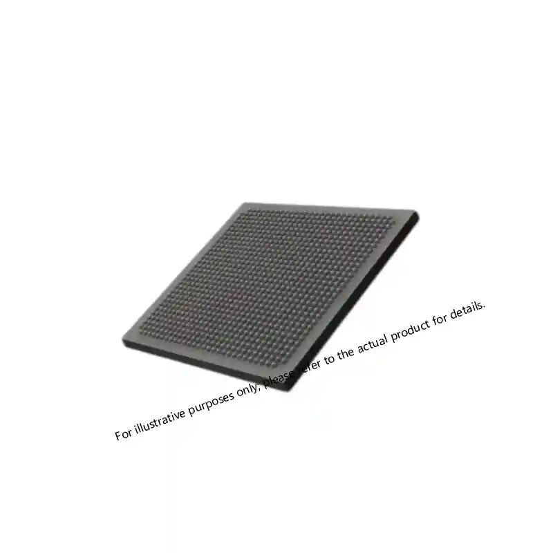
Space processing chains have moved toward flight-qualified FPGAs for payload data compression, image processing, waveform generation, and bus housekeeping. Configuration memory reliability is the central concern for SRAM-based devices, because an upset in configuration cells can change logic function. Flash-based and antifuse devices reduce this configuration upset surface, while SRAM-based designs rely on configuration scrubbing, triple-module redundancy, and careful bitstream recovery.
For payload processors, the selection sequence should evaluate configuration memory behavior under heavy-ion exposure, available single-event functional interrupt rates, and power consumption in the intended speed grade. For bus controllers, lower-power devices with proven watchdog and reset behavior often outweigh raw logic density.
Engineers working through a device-level trade study also need the supporting data for package, thermal path, and configuration endurance.
When configuration memory integrity is the limiting factor, part-level trade data can narrow the selection before board-level radiation testing.
(https://sparklemilchip.com/virtex-7-xc7vx690t-performance-and-reliability-insights/) covers packaging, thermal behavior, and long-duration reliability integration for flight-like processing chains.
Sparkle Electronics supports these selections from its FPGA & CPLD inventory, including flash-based, antifuse, and radiation-tolerant families for payload and bus roles.
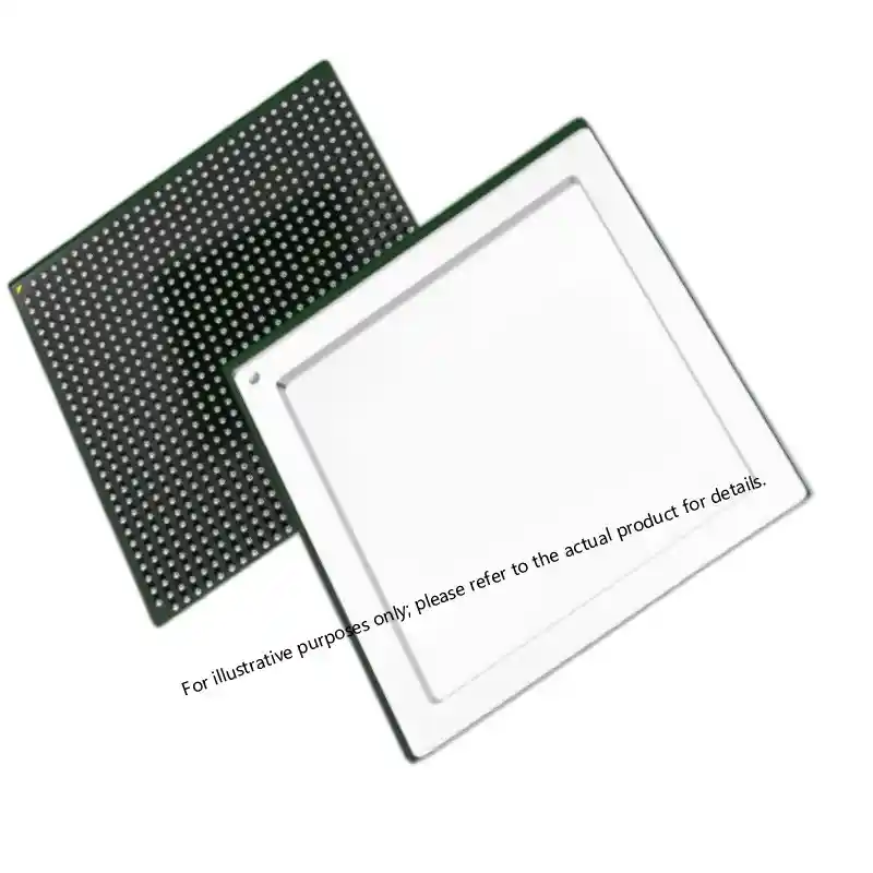
SoC-class devices with embedded processors and hardened flash configuration provide a useful middle path for compact bus computers and moderate-throughput payload controllers. The advantage is fewer board-level devices and lower power, but the procurement team must confirm temperature grade, screening flow, and configuration cell reliability before locking the design.
Data Conversion and Signal Chain
Payload performance depends heavily on the analog front end. High-speed ADCs and DACs define instantaneous bandwidth, dynamic range, and waveform fidelity for radar, imaging, communications, and scientific instruments. Space selection must consider not only sample rate and noise density but also single-event transients that can appear as momentary data errors on the converter output.
For bus applications, lower-speed converters monitor voltage, current, temperature, and actuator feedback. These parts may not require extreme sample rates, but they must remain stable through thermal cycling and stay within derated input ranges. Precision references, isolation amplifiers, and signal-conditioning circuits require the same lot-control discipline as the high-speed devices.
The High-Speed ADC/DAC category is the starting point for payload-grade converters, while analog signal-chain selections should be reviewed for low drift, stable bias, and documented burn-in results [3].
Memory, Configuration Storage, and Non-Volatile Logic
Space systems use multiple memory types for boot code, configuration storage, telemetry buffers, and science data. Rad-hard SRAM and EEPROM dominate mission-critical storage because their behavior under radiation is better understood. Error detection and correction remains necessary even with hardened memory, because single-bit upsets still occur in operational space environments.
For configuration storage, endurance and data retention after long exposure are more important than speed. Procurement should confirm that qualification data matches the exact density and package being supplied, not a generic family datasheet.
For long-lived designs, part pedigree and package traceability matter as much as nominal speed.
(https://sparklemilchip.com/a1020b-pg84b-act2-fpga-specs-sourcing-and-availability/) covers source, package, and availability factors for high-reliability logic that must remain supportable across a program.
The Memory & Storage category spans configuration memories, hardened SRAM, EEPROM, and non-volatile devices intended for high-rel integration.
Power Conversion and Distribution
Power system failures are disproportionately costly in space because a single converter or point-of-load regulator can affect multiple subsystem rails. Hi-rel DC-DC converters are selected for input range, derated output current, start-up behavior, and thermal performance in a vacuum environment. Bus power architectures usually include redundant converters, current limiting, soft-start sequencing, and independent telemetry on each rail.
For payload power, low-noise regulators and isolated converters protect sensitive analog stages. Derating rules from NASA and ECSS standards recommend conservative voltage, current, and junction temperature margins that reduce the failure rate of the assembled power network [1][2]. When a converter is not already space-qualified, upscreening may include burn-in, temperature cycling, and electrical verification against the intended application profile.
Qualification, Screening, and Lot-Level Confidence
The qualification story behind a part is often more important than the part number itself. MIL-PRF-38535 defines QML Class V and QML Class Q flows for monolithic microcircuits, while MIL-STD-883 supplies the underlying test methods for screening, burn-in, and environmental verification [3][4]. Space programs frequently add their own requirements on top of these standards, including radiation characterization, destructive physical analysis, and tighter electrical limits.
Common screening steps include pre-burn-in electrical tests, dynamic burn-in, post-burn-in electrical tests, temperature cycling, and particle impact noise detection for hermetic devices. For assembled boards, the component lot becomes the smallest unit of confidence, which is why every high-rel shipment should preserve manufacturer lot identity and date code continuity.
Upscreening commercial or industrial parts for space use is possible, but it is not the same as space qualification. The process is most successful when the original wafer lot is traceable, the package is suitable for vacuum and thermal cycling, and the screening plan is approved by the responsible engineering authority before procurement begins [1].
Send the intended screening flow and acceptable radiation budget with the initial RFQ to reduce lead-time risk. Sparkle Electronics provides compliance review and part-history verification at xuansc2144@gmail.com for space-bound BOMs.
Traceability, Documentation, and Counterfeit Control
Space procurement demands a continuous chain of custody. Certificates of conformance, screening records, radiation reports, and lot photographs should follow the parts from manufacturer through distribution to incoming inspection. For QML devices, the part number and lot identity must remain intact through repackaging, dry packing, and shipment [3][5].
Incoming inspection should verify external marking, package dimensions, lead finish, and lot consistency before the parts enter the store. For high-value or high-risk components, X-ray and decapsulation on a sample basis are common counterfeit controls. Distributors with documented quality processes in accordance with AS9120 reduce the number of uncontrolled touch points in the supply chain [5].
For space programs, the documentation package is not a post-shipment formality. It is the evidence that supports the component’s pedigree before integration. Buyers should request the complete documentation set before order release and confirm that every required certification will accompany the lot.
Long-Life Program Support and Obsolescence
Space programs often outlive the commercial lifecycle of their electronic components. Last-time buys, die banking, and technology refresh planning are necessary procurement tools for payloads and buses that may remain in service for a decade or longer. The bus side is especially sensitive because replacement of a qualified part can force board redesign and system recertification.
The component sourcing strategy should therefore combine immediate availability with continuity planning. The same distributor should be able to support prototype build, flight-lot buy, and late-program replenishment without introducing new lot risks. This is where long-term supplier qualification and approved-vendor-list status become practical program controls rather than procurement paperwork.
For a component-level review of a space payload or bus BOM, send the requirement list to xuansc2144@gmail.com. Include part numbers, quantities, target screening level, mission dose profile, and delivery window so the team can verify pedigree and lead time.
Component Request Checklist for Space Programs
Use the checklist below to align engineering and procurement before RFQ submission.
- Part number, package, and required temperature or screening suffix
- Mission orbit, duration, and expected TID or heavy-ion environment
- Required screening flow: QML Class V, QML Class Q, or approved upscreening
- Lot-level documentation needs, including C of C and radiation data
- Acceptable lead time and forecast for flight lot plus spares
- Configuration memory or upset recovery requirement for FPGAs and memory
- Board-level redundancy and derating assumptions
For a compliance and lead-time review, contact Sparkle Electronics at xuansc2144@gmail.com with the completed checklist and current BOM extract.
Frequently Asked Questions
What is the difference between payload and bus electronics?
Payload electronics perform mission-specific sensing, processing, and communication functions. Bus electronics run the spacecraft platform itself: power, command and data handling, attitude control, telemetry, and thermal management. Both require high-reliability parts, but the payload often emphasizes performance while the bus emphasizes long-duration predictable operation.
Are radiation-hardened components always required for space missions?
Not always. Mission orbit, shielding mass, duration, and system-level mitigation determine whether a design can use radiation-tolerant or upscreened hi-rel parts. Short low Earth orbit missions may use carefully selected commercial or industrial parts with approved screening, while higher-dose or safety-critical missions typically require radiation-hardened or QML Class V devices.
What does QML Class V mean?
QML Class V is a qualification and manufacturing flow defined within MIL-PRF-38535 for space-grade monolithic microcircuits. It adds stricter controls, qualification requirements, and screening compared with Class Q. The intended application and mission assurance plan determine whether Class V is required.
How are commercial components upscreened for space use?
Upscreening typically begins with lot traceability, followed by electrical testing, burn-in, temperature cycling, and sometimes radiation characterization. The process works best when the wafer or die lot can be controlled and the package is compatible with vacuum and thermal cycling conditions.
What documentation should accompany each space-qualified lot?
At minimum, the documentation package should include certificate of conformance, screening or qualification records, lot identity and date code, and any applicable radiation reports. For higher-risk components, buyers may also request X-ray, decapsulation, or destructive physical analysis records.
References
[1] NASA, “Instructions for EEE Parts Selection, Screening, Qualification, and Derating,” NASA EEE-INST-002, NASA Technical Standards Program.
[2] ECSS, “Electrical, Electronic and Electromechanical (EEE) Components,” ECSS-Q-ST-60C Rev. 2, European Cooperation for Space Standardization.
[3] U.S. Department of Defense, “Integrated Circuits (Microcircuits) Manufacturing, General Specification for,” MIL-PRF-38535.
[4] U.S. Department of Defense, “Test Method Standard for Microcircuits,” MIL-STD-883.
[5] SAE International, “Quality Management Systems – Requirements for Aviation, Space, and Defense Distributors,” AS9120B.
If you’re interested, check out these related articles:
Virtex-7 XC7VX690T: Performance, Reliability, and Integration
Virtex-7 690T FPGA: Performance for Mission-Critical Systems
Virtex-7 XC7VX690T: Performance and Reliability Insights