V24C12M100B 24V to 12V 100W DC-DC Module Sourcing Guide
Table of Contents
- Start With the Actual Load and Source Conditions
- Confirm the BCK Package and Cooling Path
- Protect the Input and Output Rail
- Dynamic Loads From FPGAs and Processors
- Procurement Evidence and Incoming Inspection
- Sourcing Support for V24C12M100B
- FAQ
- Is the V24C12M100B a drop-in replacement for older 24 V to 12 V converters?
- What input range should the design assume?
- How much cooling does the module require?
- What documentation should be required before accepting parts?
The V24C12M100B is a 24 V nominal input, 12 V output, 100 W DC-DC module for power distribution in defense, aerospace, and high-reliability systems. The part number defines a power stage, not a complete power solution. Successful use depends on the exact source, load, cooling, and documentation path around it. Engineers and procurement teams should review the module as one element of an evidence chain, from electrical derating and mechanical fit to traceability and incoming inspection.
Start With the Actual Load and Source Conditions
The first question is not whether the module can convert 24 V to 12 V. It is whether the input source stays within the module’s operating envelope under the system’s worst transient. A nominal 24 V input may have surges, sags, or noisy events depending on the aircraft, vehicle, or industrial source. If the source has not been reviewed against the actual bus, the module may shut down or degrade when the system needs it most. Request the production input range and transient response data when they are not already in the approved source-control drawing.
| Check | What to confirm | Why it matters |
|---|---|---|
| Input source | Steady-state range, ripple, surge, dropout | Avoids unintended shutdown |
| Load current | Average, peak, inrush, pulsed load | Validates 100 W use and thermal stress |
| Output capacitor | ESR, total capacitance, placement | Prevents instability |
| Remote sense | Required or prohibited | Avoids regulation error |
| Fault mode | Overcurrent, overvoltage, thermal response | Coordinates protection |
Do not infer that the 24 V and 12 V markings in the part number remove the need for source and load verification. They identify the nominal conversion function, while the actual operating limits are set by the module family’s electrical specification and the end system environment.
Confirm the BCK Package and Cooling Path
Package designation BCK describes the mechanical and thermal interface, not simply a form factor. Before committing to layout, confirm the outline, pin length, baseplate dimensions, and permissible mounting torque. The module’s heat is removed through the baseplate and available airflow. A mechanical fit that ignores the thermal path can pass a dimensional check but fail in operation.
Determine whether the mounting surface is flat, whether thermal interface material is required, and whether the cooling design can handle the dissipated power at the highest ambient. These details should be compared with the manufacturer’s mechanical drawing and derating curves. At 100 W output, even a small efficiency difference creates several watts of dissipated heat. Baseplate temperature is a more useful acceptance check than room temperature alone because it reflects the internal component stress.
Protect the Input and Output Rail
Defense and aerospace power buses are not clean DC. The V24C12M100B installation should include input transient protection and output filtering suitable for the load. Start with external fuse or circuit breaker coordination, because the module’s internal protection is not a substitute for system-level fault clearing. Input filter components should be selected with the source impedance and electromagnetic compatibility requirements in mind.
Output capacitance should follow the manufacturer’s guidance rather than a rule of thumb. Too much capacitance can affect start-up and short-circuit behavior. Too little can produce excessive ripple for sensitive analog or digital circuits.
| RFQ field | What to request |
|---|---|
| Input | Source voltage range, transient limit, source impedance |
| Output | Load current profile, allowable ripple, regulation band |
| Cooling | Baseplate temperature, airflow, mounting surface |
| Compliance | Certificate of conformance, traceability, screening records |
| Delivery | Quantity, lead time, packaging, shelf-life requirement |
Ask for this information as part of the RFQ rather than treating the part number as the only specification detail.
Dynamic Loads From FPGAs and Processors
Many V24C12M100B applications do not supply a constant resistive load. They power FPGAs, ADCs, CPLDs, and other logic devices that create fast current steps. A load step can cause a temporary output voltage excursion before the converter control loop responds. The acceptable deviation depends on the downstream device tolerance. SmartFusion2, ProASIC3, ACT2, and SX-A devices can present different inrush profiles and switching activity. These loads must be considered when budgeting output capacitors, remote sense, and startup sequencing.
The images below show examples of high-reliability logic devices that may share a 12 V rail or the subsequent point-of-load stage. They are not electrically interchangeable, but they illustrate why load characterization is necessary.
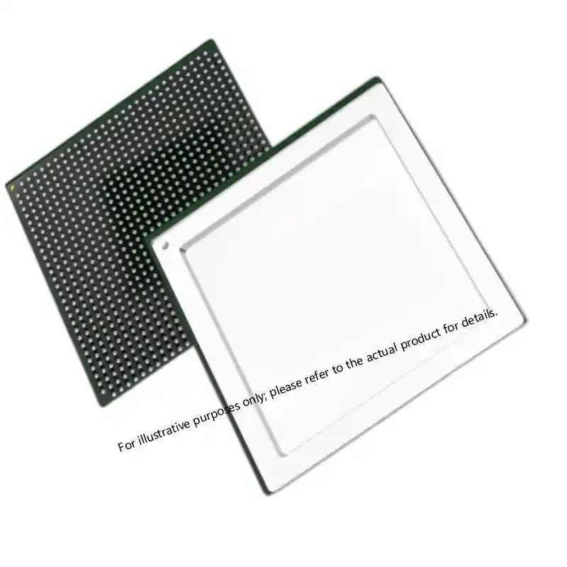
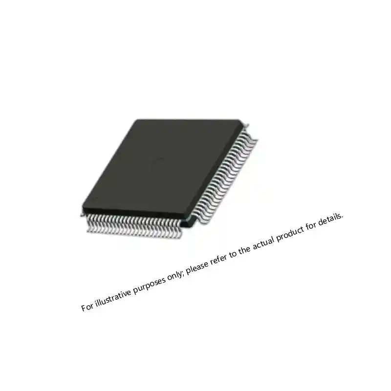
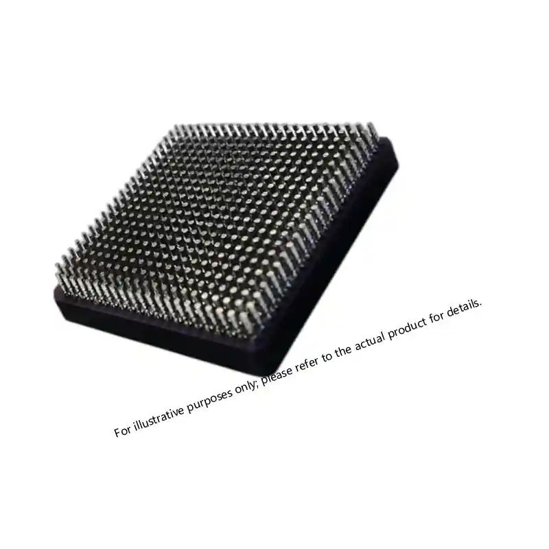
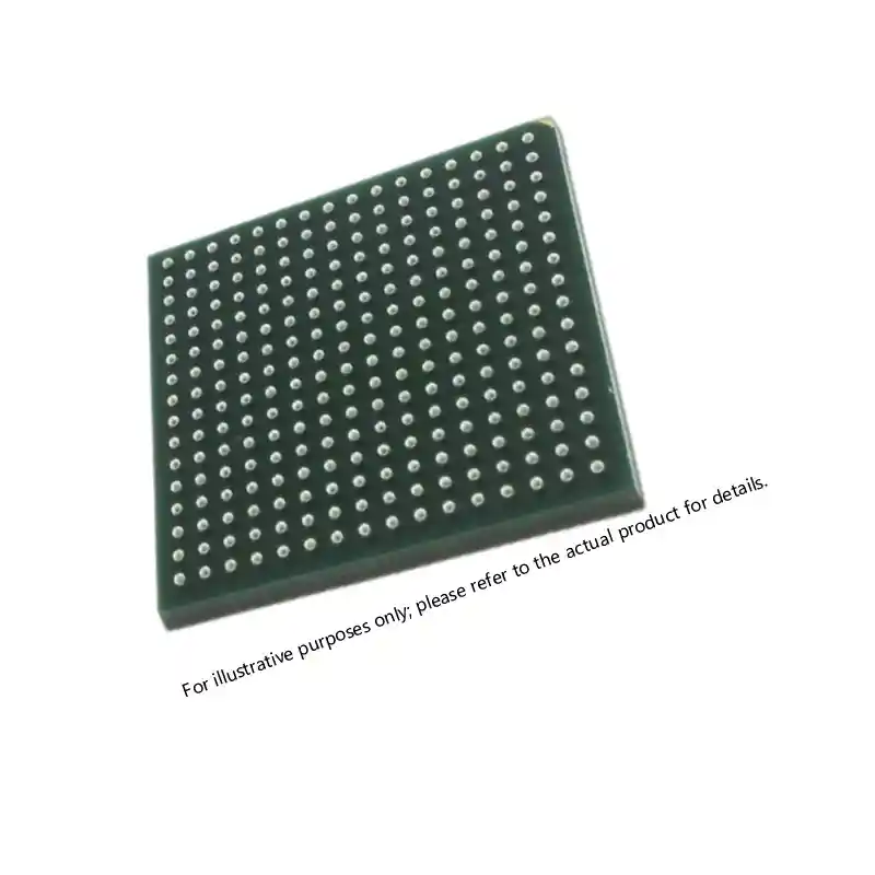
A 12 V rail that feeds multiple logic devices must remain stable during fast load steps and startup. <A1020B-PG84B ACT2 FPGA: Specs, Sourcing, and Availability> covers sourcing and availability considerations for one representative hi-rel logic device on that rail.
Procurement Evidence and Incoming Inspection
For a military or aerospace program, the part number alone does not establish authenticity or compliance. The procurement record should include the manufacturer, date code, lot code, country of origin, and any required screening or conformance documentation. If the module is a qualified version, the associated certificate should be traceable to that specific shipment. If the requirement is for a less severe application, the acceptance basis should still be documented.
Before releasing parts to stock, perform these checks:
- Compare labels, part number, and package markings to the approved source-control drawing.
- Confirm continuity between the purchase order, packing slip, and certificate of conformance.
- Check lead condition and packaging for signs of prior installation or handling.
- Record lot and date codes before the parts enter stock, since later traceability may be harder.
Do not let an incoming inspection checklist become a substitute for verifying that the documents actually belong to the parts in front of you. A certificate that cannot be matched to the package is not evidence of compliance.
Sourcing Support for V24C12M100B
Send Sparkle Electronics the known part number, input source, load profile, cooling method, compliance evidence, and target schedule. A focused RFQ with those details makes stock check and documentation review faster. Contact Sparkle Electronics at xuansc2144@gmail.com.
FAQ
Is the V24C12M100B a drop-in replacement for older 24 V to 12 V converters?
Not automatically. Match input range, output regulation, pinout, mechanical dimensions, thermal path, and protection behavior before substituting. The same nominal 24 V to 12 V conversion can hide differences in transient response, remote sense, and package height.
What input range should the design assume?
Use the manufacturer’s production data for the specific V24C12M100B rather than assuming a generic range. Include transients, sags, and source impedance in the worst-case analysis. A nominal 24 V bus does not always remain within the module’s steady-state limits.
How much cooling does the module require?
Baseplate temperature and airflow determine the actual available power. Confirm derating curves, mounting surface, thermal interface material, and maximum ambient. At 100 W output, a few watts of dissipation can make the thermal design the limiting factor.
What documentation should be required before accepting parts?
Request a certificate of conformance, lot and date code records, traceability to the supplier chain, and any test or screening evidence required by the program. Match the documents to the received parts and keep the records with the lot.
If you’re interested, check out these related articles:
A1020B-PG84B ACT2 FPGA: Specs, Sourcing, and Availability
Virtex-7 690T FPGA: Performance for Mission-Critical Systems
XCKU115 UltraScale FPGA: Powering Critical Defense Systems