V24A28M400BG DC-DC: 24V to 28V/400W Sourcing Guide
Table of Contents
- What the V24A28M400BG Designation Tells You
- Electrical Parameters to Confirm Before Purchase
- Mechanical, Thermal, and Packaging Checks
- Compliance and Use in 28 V Defense Systems
- Compatible Control and Monitoring Components
- Sourcing Support for V24A28M400BG
- FAQ
- Is the V24A28M400BG a military-qualified part by itself?
- What should I confirm instead of relying only on the part number?
- Does the BG package indicate a standard pin length or baseplate?
- Can this converter be used for MIL-STD-704 or MIL-STD-1275 designs?
- What documentation should I require to avoid counterfeit or gray-market risk?
V24A28M400BG is a 24 V input, 28 V output DC-DC converter rated at 400 W. For procurement and design teams working on high-reliability power systems, the part number is a useful selection screen, but it is not by itself evidence of qualification, screening level, or form fit. The buyer should verify the exact electrical, mechanical, thermal, and documentation requirements against the manufacturer’s formal data before committing the part to a mission-critical 28 V bus.
What the V24A28M400BG Designation Tells You
The part number groups the converter into a 24 V nominal input family, 28 V output, 400 W output rating, and a BG package designation. That is enough to begin sourcing, but it should not replace a detailed review.
| Designator | Likely meaning | Action for buyer |
|---|---|---|
| V24A | 24 V nominal input family | Confirm full minimum and maximum input range |
| 28 | 28 V nominal output | Confirm output setpoint and trim range |
| M | Temperature or product grade designator | Do not read it as MIL qualification by itself |
| 400 | 400 W rated output | Derate for temperature, airflow, and actual input voltage |
| BG | Mechanical or package option | Confirm pin length, baseplate, and outline drawing |
At full rated power and 28 V output, the rated output current is approximately 14.3 A. This follows directly from 400 W divided by 28 V and is a reference number only. The actual safe operating point depends on input range, baseplate temperature, airflow, derating, output trim, and the application load profile.
Electrical Parameters to Confirm Before Purchase
A part-number match is not technical acceptance. The buyer should compare the converter’s formal electrical data with the actual board conditions, especially when the module feeds a 28 V defense or avionics bus.
| Parameter | What to request | Why it matters |
|---|---|---|
| Input voltage | Minimum, maximum, and transient limits | Prevents shutdown or damage under a disturbed bus |
| Output voltage | Nominal setpoint and trim range | The 28 V bus may require a tighter regulated window |
| Load profile | Continuous, peak, and capacitive loading | Affects stability, inrush, and thermal stress |
| Efficiency and derating | Efficiency curves by load and temperature | Determines cooling and worst-case input current |
| Protection | Undervoltage, overvoltage, current limit, and thermal shutdown | Defines behavior during faults and startup |
| Output current | Full-load current and short-circuit limits | Confirms margin above the 14.3 A reference point |
Mechanical, Thermal, and Packaging Checks
BG is a package code, not a complete mechanical definition. Buyers should obtain the manufacturer outline drawing and compare it with the actual board envelope, pin pitch, baseplate surface, and mounting method. In high-reliability power designs, thermal interface flatness and mounting force can be just as important as the electrical rating.
Ask whether the module has a baseplate, what pin length applies to the exact order option, and whether the converter is intended for through-hole mounting, chassis mounting, or thermal-interface use. Physical inspection should confirm that markings, date codes, and package features match the documentation before the part enters production inventory.
Compliance and Use in 28 V Defense Systems
A DC-DC converter with a 28 V output can support defense vehicles, avionics, naval electronics, and ground systems, but system-level compliance remains the program’s responsibility. MIL-STD-704 and MIL-STD-1275 define requirements for aircraft and vehicle power buses. A module suited to a nominal 28 V bus still needs input transient protection, EMI filtering, and system validation.
Do not infer that the converter alone makes a platform compliant.
| Question | What it tells you | What it does not tell you |
|---|---|---|
| Is the input/output rating suitable? | The part number indicates a 24 V to 28 V, 400 W screen | Actual derating, load, and transient margins |
| Is it qualified for my program? | The designation is visible | Manufacturer qualification data or program-specific testing |
| Is the package correct? | BG package code is present | Exact mounting, pin length, and thermal interface |
| Is the supply chain safe? | The seller presents it as such | Documentation, lot history, and traceability |
Compatible Control and Monitoring Components
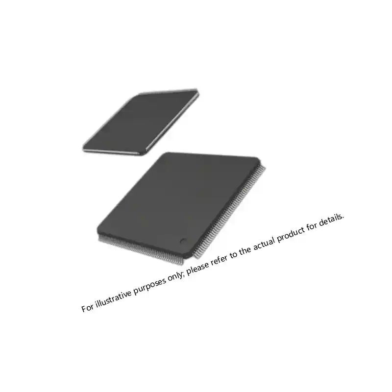
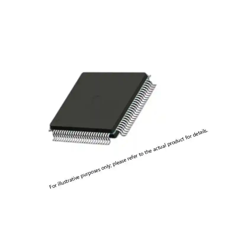
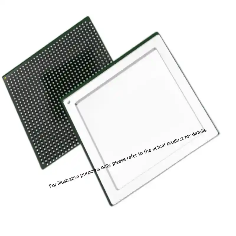
In many 24 V defense power architectures, the converter is paired with an FPGA or CPLD for sequencing, monitoring, and fault response. The controller may read power-good signals, trim or enable commands, and system telemetry. Procurement teams frequently need to align the converter with the logic and memory parts on the same board to avoid separate documentation and revision mismatches.
Power-management logic in a 24 V board often changes with the central processor or FPGA architecture. <XCKU085 UltraScale FPGA: Performance for Critical Systems> covers the platform decisions that affect startup, shutdown, and monitor timing around the converter.
The following representative companion logic devices are commonly evaluated on the same high-power converter card:
Sourcing Support for V24A28M400BG
Specify the exact part number, required date codes, packaging, and the documentation package your program requires. The more complete the RFQ, the easier it is to separate a genuine, traceable supply path from an unverified source.
Send the following information with your V24A28M400BG inquiry:
- Nominal and transient input voltage range
- Output setpoint and trim requirements
- Continuous, peak, and capacitive load profile
- Cooling method and baseplate temperature
- Package, pin length, and mounting requirement
- Required screening, certificate of conformance, and test data
- Application environment and system standard
Sparkle Electronics can review the requirement, confirm available stock and documentation, and support the sourcing path. Email your requirement to xuansc2144@gmail.com.
FAQ
Is the V24A28M400BG a military-qualified part by itself?
The part number identifies a high-power 24 V to 28 V DC-DC converter, not a completed qualification. The M designator may indicate a product or temperature grade rather than MIL-SPEC approval. Ask for manufacturer qualification records and program-specific testing before treating the module as a qualified hi-rel component.
What should I confirm instead of relying only on the part number?
Confirm the input voltage range, output setpoint, load profile, thermal conditions, actual package drawing, and required documentation. A part-number match identifies the general device, but it does not verify that an incoming lot is authentic, correctly packaged, and suitable for your board.
Does the BG package indicate a standard pin length or baseplate?
BG identifies the package option, but pin length, baseplate, and mounting details can vary by order option and revision. Request the manufacturer outline drawing and compare the mechanical features against the actual sample and board layout.
Can this converter be used for MIL-STD-704 or MIL-STD-1275 designs?
A nominal 28 V output is a useful starting point, but the complete power input usually needs transient suppression, EMI filtering, and system-level validation. Do not treat the module alone as a compliance solution for an aircraft or vehicle power bus.
What documentation should I require to avoid counterfeit or gray-market risk?
Require a valid certificate of conformance, lot or date code traceability, manufacturer part number and marking consistency, packaging condition, and photographs before shipment. For high-reliability programs, add any required test records to the documentation package.
If you’re interested, check out these related articles:
Virtex-7 690T FPGA: Performance for Mission-Critical Systems
Virtex-7 XC7VX690T: Performance and Reliability Insights
XCKU115 UltraScale FPGA: Powering Critical Defense Systems
Virtex-7 XC7VX690T: Performance, Reliability, and Integration