Hi-Rel Miniaturized Components for Body-Worn Military Systems
Table of Contents
- Why Body-Worn Military Electronics Require Specialized Components
- How SWaP-C Constraints Drive Component Selection
- What FPGA and Processor Options Suit Wearable Military Applications
- Which Power Management Components Meet Miniaturization Requirements
- How Passive Components Affect Miniaturized System Reliability
- What Memory and Storage Options Support Wearable Form Factors
- How to Source Hi-Rel Miniaturized Components Without Supply Chain Risk
- What Testing and Qualification Requirements Apply to Body-Worn Components
- Common Questions About Body-Worn Military Component Selection
- Can commercial components be upscreened for body-worn military applications?
- How do I determine if a miniaturized package will survive body-worn mechanical stresses?
- What is the typical lead time for miniaturized military-grade FPGAs?
- How does power consumption compare between flash-based and SRAM-based FPGAs for body-worn applications?
- What documentation should I expect when sourcing hi-rel miniaturized components?
- Sources and Further Reading
Soldiers carrying electronic systems on their bodies face a fundamental engineering constraint that shapes every component decision: the device must function reliably under combat conditions while adding minimal weight and bulk. Body-worn military electronics, including tactical radios, wearable sensors, heads-up displays, and biometric monitors, demand components that survive extreme temperatures, shock, vibration, and electromagnetic interference while consuming as little power as possible. Selecting the wrong component for these applications does not merely cause a field failure; it compromises mission effectiveness and puts personnel at risk. This article examines the technical requirements, component categories, and sourcing considerations that defense programs must address when specifying hi-rel miniaturized components for body-worn military systems.
Why Body-Worn Military Electronics Require Specialized Components
Body-worn systems operate in an environment that commercial electronics never encounter. A soldier moving through desert terrain may experience ambient temperatures exceeding 50°C, while the same equipment must function hours later in an air-conditioned vehicle or during a night operation where temperatures drop below freezing. MIL-PRF-38535 Class Q and Class V devices are screened to operate across the full military temperature range of -55°C to +125°C, a specification that exists precisely because body-worn equipment cannot rely on controlled thermal environments.
Shock and vibration present equally demanding challenges. A radio mounted on a plate carrier experiences repeated impacts from running, jumping, and prone-to-standing transitions. MIL-STD-810 Method 516 specifies shock testing up to 40g for equipment carried by personnel, and components that pass commercial drop tests routinely fail under these sustained mechanical stresses. I have seen programs discover this gap late in qualification when accelerated life testing reveals solder joint failures on components that performed flawlessly on the bench.
Electromagnetic compatibility adds another layer of complexity. Body-worn systems operate in close proximity to other electronic equipment, including vehicle systems, communications gear, and electronic warfare assets. Components must meet MIL-STD-461 emissions and susceptibility requirements, which often drives the selection of shielded packages and specific grounding configurations that commercial equivalents lack.
How SWaP-C Constraints Drive Component Selection
Size, Weight, Power, and Cost (SWaP-C) optimization is not an abstract goal for body-worn systems; it directly affects how long a soldier can operate before fatigue degrades performance. Every gram matters when equipment is carried for 12-hour patrols, and every milliwatt of power consumption determines battery weight and mission duration.
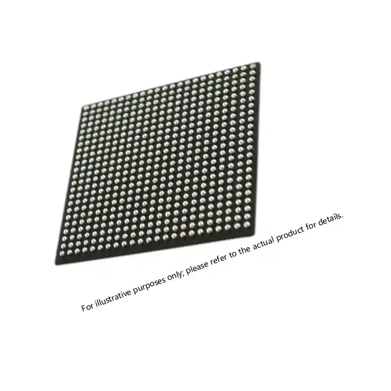
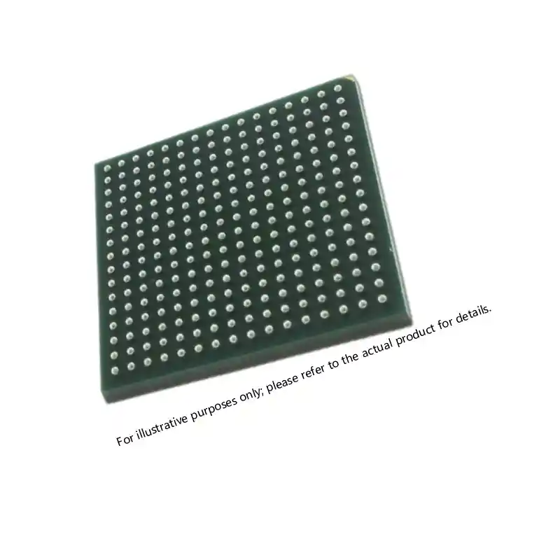
Miniaturized packaging has become the primary response to size and weight constraints. Ball Grid Array (BGA) and Chip Scale Package (CSP) formats reduce footprint by 40% to 60% compared to traditional leaded packages while maintaining the same die functionality. The A3P1000-FGG484I ProASIC3 FPGA, for example, delivers one million gates in a 484-ball fine-pitch BGA package measuring just 23mm × 23mm, enabling integration into wearable form factors that would be impossible with larger package options.
| Component Category | Typical Body-Worn Application | Key SWaP-C Parameter |
|---|---|---|
| Low-power FPGA | Sensor fusion, encryption | Static power < 50mW |
| High-efficiency DC-DC | Power distribution | Efficiency > 90% at light load |
| Miniature ADC | Biometric signal acquisition | Package height < 1.5mm |
| Low-power MCU | System control | Sleep current < 1µA |
| Compact memory | Data logging, boot storage | Density > 1Gb in 8×6mm BGA |
Power consumption optimization requires examining not just active current but sleep modes and wake-up times. Body-worn systems spend significant time in standby, waiting for events that trigger full operation. Components with deep sleep modes drawing microamps rather than milliamps extend battery life dramatically. The selection process must evaluate the complete power profile across all operating states, not just peak consumption during active processing.
What FPGA and Processor Options Suit Wearable Military Applications
Field Programmable Gate Arrays serve as the processing backbone for many body-worn systems because they combine reconfigurability with the ability to implement custom signal processing chains optimized for specific sensor types. The challenge lies in finding devices that deliver sufficient logic density and I/O count in packages small enough for wearable integration while meeting military temperature and reliability requirements.
Microchip (formerly Microsemi/Actel) ProASIC3 and SmartFusion2 families have become common choices for body-worn applications. The A3P1000-FG256I offers one million system gates with 256 I/O in a 256-ball fine-pitch BGA, providing a balance between capability and footprint that suits helmet-mounted displays and wrist-worn computing units. For applications requiring integrated analog functions, the SmartFusion2 M2S150-FCVG484I combines 150,000 logic elements with hardened memory controllers and analog-to-digital conversion in a single device, eliminating the need for separate analog front-end components.
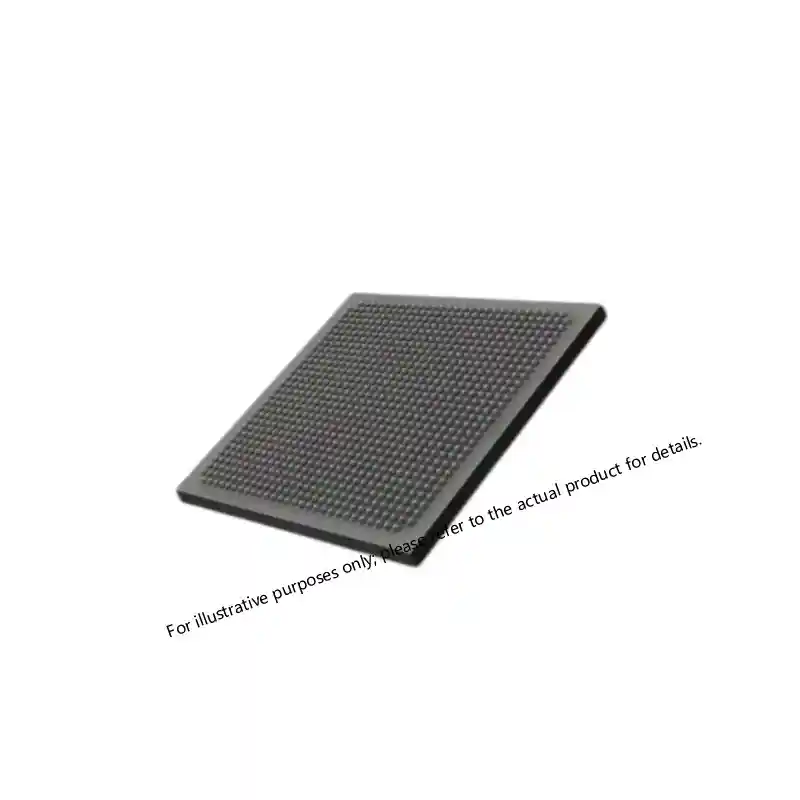
Flash-based FPGAs offer a specific advantage for body-worn systems: instant-on operation. Unlike SRAM-based devices that require configuration loading at power-up, flash-based FPGAs retain their configuration through power cycles and begin operating within microseconds of power application. This characteristic matters for systems that must respond immediately to threats or commands without waiting for boot sequences.
When processing requirements exceed what a single FPGA can deliver efficiently, programs often turn to multi-chip module (MCM) solutions or System-in-Package (SiP) configurations that combine an FPGA with a processor and memory in a single package. These approaches reduce board area and interconnect parasitics while simplifying thermal management, though they require careful attention to supply chain considerations since MCM devices may have longer lead times than discrete components.
Which Power Management Components Meet Miniaturization Requirements
Power management represents one of the most challenging aspects of body-worn system design because the components must handle significant power conversion while occupying minimal board space and generating minimal heat. Traditional approaches using discrete regulators and external inductors consume too much area for wearable applications.
Integrated power modules have emerged as the preferred solution. VICOR’s DCM series, including devices like the DCM3623T36G31C2T00, packages a complete DC-DC converter with magnetics in a surface-mount format that delivers 3.3V at 6A from a 36V input. This level of integration eliminates the need for external inductors and reduces the component count for a power rail from a dozen discrete parts to a single device.
For lower-power rails, linear regulators with ultra-low quiescent current become essential. The TPS73633MDBVREP delivers 400mA at 3.3V with quiescent current under 1µA in shutdown mode, packaged in a SOT-23-5 footprint that occupies less than 3mm². When a body-worn system includes multiple voltage rails, each with different load profiles, selecting regulators with appropriate quiescent current for each rail can reduce standby power consumption by an order of magnitude compared to using a single regulator type throughout.
Battery charging and management ICs must also meet military temperature requirements, which eliminates most commercial battery management solutions. Programs often find that the charging IC becomes the limiting factor for system temperature range because commercial devices typically specify only 0°C to 70°C operation.
How Passive Components Affect Miniaturized System Reliability
Passive components, including capacitors, resistors, and inductors, often receive less attention than active devices during component selection, yet they frequently determine system reliability in body-worn applications. A ceramic capacitor that cracks under thermal cycling or a resistor that drifts out of tolerance at temperature extremes will cause system failure just as surely as a processor malfunction.
MIL-PRF-55681 and MIL-PRF-123 establish reliability requirements for military-grade capacitors, specifying screening levels and failure rate requirements that commercial components do not meet. The M39014/01-1553V ceramic capacitor, for example, undergoes 100% screening including thermal shock, burn-in, and electrical testing that identifies infant mortality failures before the component ships.
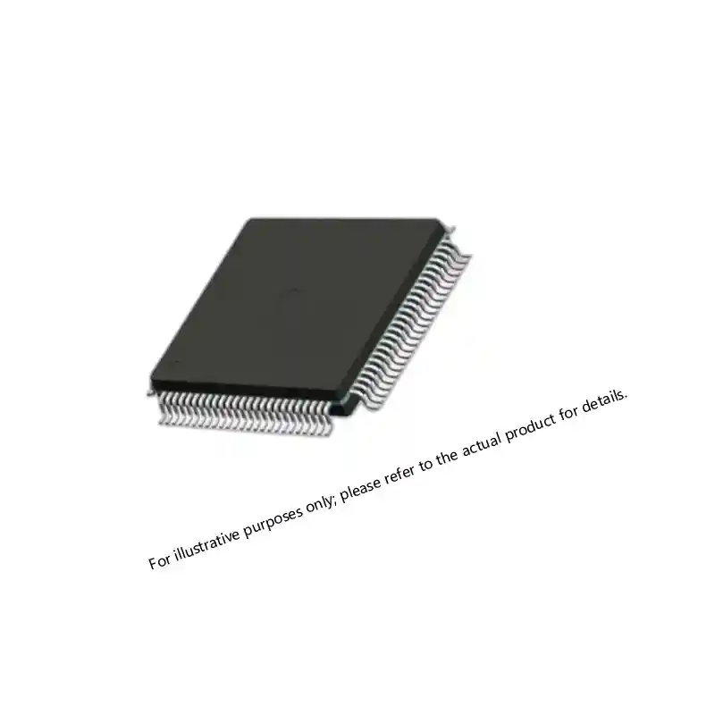
Tantalum capacitors present particular challenges in body-worn systems because they offer high capacitance density but can fail catastrophically if subjected to voltage transients or reverse bias. MIL-PRF-39003 qualified tantalum capacitors like the M39003/01-2775J include surge current testing and derating requirements that reduce field failure rates, but designers must still apply appropriate derating, typically 50% of rated voltage for military applications, to achieve acceptable reliability.
Connector selection for body-worn systems requires balancing miniaturization against the need for secure, reliable mating under field conditions. Micro-D connectors meeting MIL-DTL-83513 provide a standardized solution with proven reliability, though newer nano-connector formats offer further size reduction for applications where standard micro-D footprints cannot fit.
What Memory and Storage Options Support Wearable Form Factors
Body-worn systems require memory for program storage, data logging, and working memory for signal processing algorithms. The memory subsystem must survive power interruptions without data loss while fitting within the system’s size and power budget.
Non-volatile memory for boot and configuration storage typically uses serial NOR flash devices. The EPCQ128ASI16N provides 128Mb of serial configuration memory in a 16-pin SOIC package, supporting FPGA configuration and system boot code storage. For applications requiring faster access, parallel NOR flash remains available in military-grade versions, though the larger package sizes and higher pin counts make these devices less attractive for miniaturized systems.
Working memory for signal processing typically uses SRAM for its speed and unlimited write endurance. The ACT-S512K32N-017P7Q provides 512K × 32 organization with 17ns access time in a radiation-tolerant package, suitable for applications where single-event upset immunity matters. For systems operating in benign radiation environments, commercial-grade SRAM with appropriate screening can provide adequate performance at lower cost.
Data logging applications increasingly use NAND flash for its density advantage, though wear leveling and bad block management add complexity. Programs must evaluate whether the firmware overhead for flash management fits within their processing budget and whether the write endurance meets mission life requirements.
How to Source Hi-Rel Miniaturized Components Without Supply Chain Risk
Sourcing miniaturized hi-rel components presents challenges that do not exist for standard military-grade devices. Many miniaturized package options are available only in commercial or industrial temperature grades, forcing programs to choose between the package they need and the screening level they require. Upscreening, where commercial devices undergo additional testing to verify operation over military temperature ranges, can bridge this gap but adds cost and lead time while providing less assurance than devices designed and qualified for military use from the start.
Lead times for miniaturized military components frequently exceed 26 weeks, and some devices reach 52 weeks or longer during periods of high demand. Programs that wait until detailed design is complete before placing component orders often discover that their schedule cannot accommodate these lead times. Early engagement with distributors who maintain stock of hi-rel miniaturized components can reduce this risk significantly.
| Sourcing Consideration | Risk if Ignored | Mitigation Approach |
|---|---|---|
| Package availability in military grade | Forced redesign or upscreening | Verify military-grade availability before design commit |
| Lead time for miniaturized packages | Schedule slip | Pre-order or use stocking distributor |
| Obsolescence of miniaturized devices | Lifetime buy requirement | Monitor product lifecycle, plan for alternatives |
| Counterfeit risk for small packages | Field failures, safety risk | Source only from authorized or trusted distributors |
| Documentation for miniaturized parts | Qualification delays | Confirm datasheet and qualification report availability |
Counterfeit risk increases with component miniaturization because smaller packages are easier to remark and harder to inspect visually. Working with distributors who maintain full traceability and perform incoming inspection per AS6081 standards provides essential protection. Sparkle Electronics maintains inventory of over 500 military-grade part numbers with complete chain-of-custody documentation, enabling programs to source authenticated components without the lead time delays of direct OEM orders.
If your body-worn system program requires specific miniaturized components not commonly stocked, it is worth discussing your requirements early. Share your part numbers and quantities with xuansc2144@gmail.com to confirm availability and lead times before finalizing your BOM.
What Testing and Qualification Requirements Apply to Body-Worn Components
Components destined for body-worn military systems must demonstrate reliability under conditions that simulate actual use. MIL-STD-883 establishes test methods for integrated circuits, including thermal cycling (Method 1010), mechanical shock (Method 2002), and constant acceleration (Method 2001). Components qualified to MIL-PRF-38535 have undergone these tests as part of their qualification, but programs often impose additional requirements based on specific application stresses.
Highly Accelerated Life Testing (HALT) and Highly Accelerated Stress Screening (HASS) provide additional assurance beyond standard military qualification. These tests apply combined temperature and vibration stresses that exceed specification limits to identify design margins and latent defects. While not required by military specifications, HALT and HASS have become common practice for body-worn systems where field failure consequences are severe.
Electromagnetic compatibility testing per MIL-STD-461 applies at the system level rather than the component level, but component selection directly affects system-level EMC performance. Components with internal decoupling, controlled rise times, and appropriate grounding provisions simplify system-level EMC compliance. Conversely, components that generate excessive switching noise or lack adequate internal filtering can make system-level compliance difficult or impossible to achieve.
Common Questions About Body-Worn Military Component Selection
Can commercial components be upscreened for body-worn military applications?
Upscreening can verify that specific lots of commercial components operate over military temperature ranges, but it does not provide the same assurance as devices designed and qualified for military use. Commercial devices may use materials, processes, or design rules that limit their reliability under extended temperature exposure even if they pass initial screening. Programs should use upscreening as a last resort when military-grade equivalents are unavailable, not as a cost reduction strategy. If your application requires upscreening, confirm the test protocol and acceptance criteria with your supplier before committing.
How do I determine if a miniaturized package will survive body-worn mechanical stresses?
Package reliability under mechanical stress depends on the solder joint configuration, substrate material, and underfill requirements. BGA packages with appropriate underfill typically survive higher shock and vibration levels than leaded packages, but the specific survival threshold depends on board design, assembly process, and component mass. Request package qualification data from the manufacturer and compare the tested stress levels against your application requirements. For critical applications, plan for board-level qualification testing that replicates your specific mounting configuration.
What is the typical lead time for miniaturized military-grade FPGAs?
Lead times for military-grade FPGAs in miniaturized packages typically range from 26 to 52 weeks when ordering directly from manufacturers. Stocking distributors who maintain inventory of common devices can reduce this to days or weeks for available part numbers. The lead time situation changes frequently based on demand and manufacturing capacity, so confirming current availability before design commitment is essential. Reach out with your specific part numbers to get current lead time estimates.
How does power consumption compare between flash-based and SRAM-based FPGAs for body-worn applications?
Flash-based FPGAs generally offer lower static power consumption than SRAM-based devices of equivalent logic density because they do not require continuous refresh of configuration memory. This advantage becomes significant in body-worn applications where systems spend extended periods in standby. However, SRAM-based FPGAs may offer higher performance and greater logic density in equivalent package sizes. The optimal choice depends on your specific power budget, performance requirements, and whether instant-on operation matters for your application.
What documentation should I expect when sourcing hi-rel miniaturized components?
Authentic military-grade components should come with Certificates of Conformance (C of C) that reference the applicable military specification, lot date codes, and test results. QML-qualified devices include qualification data that demonstrates compliance with MIL-PRF-38535 requirements. For components sourced through distribution, you should also receive traceability documentation showing the chain of custody from the original manufacturer. If a supplier cannot provide complete documentation, that gap represents a significant risk that the components may not meet specification requirements.
Sources and Further Reading
Defense Logistics Agency — MIL-PRF-38535 General Specification for Integrated Circuits, 2023
Defense Standardization Program — MIL-STD-810H Environmental Engineering Considerations, 2019
Microchip Technology — ProASIC3 FPGA Family Datasheet, 2024
If you’re interested, check out these related articles:
Virtex-7 690T FPGA: Performance, Packaging, and Reliability Insights
Virtex-7 XC7VX690T: Performance and Reliability Insights
UltraScale KU085 FPGA Specifications for Defense Systems