Design for Reliability (DfR) in Military Electronic Systems
Table of Contents
- Why DfR Is a Program-Leveraging Investment
- Design and Derating Practices That Improve Reliability
- Component Selection, Qualification, and Supply Chain Execution
- Component Derating and Selection Criteria
- Reliability Testing and Qualification
- Supply Chain Integrity
- Ensuring Your Program’s DfR Starts with the Right Components
- Common Questions About Military DfR
- How is DfR different from reliability testing?
- Should I always select QML-V parts for space programs?
- Can upscreened commercial components match military-grade reliability?
- How do I manage DfR for a program with obsolescent components?
Design for reliability in military electronic systems is not a check-the-box review that happens after the design is finished. It begins with the first component entered on the bill of materials and continues through every procurement decision, layout change, and qualification test. Most of the field failures I have investigated across defense programs trace back not to a simulation overlooked during design, but to a component-level choice, a part that was not derated sufficiently, a lot whose source documentation was incomplete, or a lifecycle risk that surfaced only after the system was already in sustainment. This article outlines the DfR practices that directly affect reliability outcomes, from early design decisions through component selection and supply chain execution, based on what I have seen produce verifiable results in real programs.
Why DfR Is a Program-Leveraging Investment
A military electronic system that fails during a mission creates consequences far beyond the cost of a replacement board. A radar processor that drops timing lock, an engine controller that resets at temperature extremes, or a munitions safety-and-arming circuit that behaves unpredictably can force a program back into redesign, qualification, and sometimes recertification, consuming months the program cannot afford. I have seen programs absorb schedule delays exceeding eighteen months because a single reference oscillator that passed bench testing exhibited drift across the full thermal-vibration profile. That schedule loss, plus the cost of redesign, stocked inventory write-off, and re-qualification testing, multiplies the initial component cost by several orders of magnitude.
DfR shifts that risk left in the schedule. When a program invests in reliability analysis during architecture definition, that analysis informs derating policy, component technology selection, and supplier qualification requirements before any schematic is finalized. The return is not theoretical. Programs that executed a proper DfR analysis before design freeze show measurably fewer field returns and sustainment surprises than programs that delegated reliability to final qualification alone. For a defense prime, that translates into predictable program milestones, stable production lanes, and a supplier base that can plan long-cycle wafer and packaging commitments.
Design and Derating Practices That Improve Reliability
Derating is the single most methodical lever a design team can pull to increase system reliability, but it must be applied with an understanding of what the part actually sees in service, not just a blanket percentage applied to datasheet limits. For military electronics, the thermal environment, vibration spectrum, and transient electrical stresses are rarely uniform across a board, and derating that does not account for hot spots or mechanical resonance can create a false sense of margin.
Start with a thermal map before assigning derating factors. An FPGA placed near a DC-DC converter with limited copper pour will run hotter than the same part in an open area, and derating its I/O supply current at 85°C ambient means little if the junction temperature under load is already 15°C higher. For high-speed ADCs such as the AD9680 or AD9694 families, clock jitter and power supply noise can erode effective number of bits, so derating the analog supply rail alone is not enough, the digital supply rail and reference voltage stability must be analyzed thermally as well.
For passives, the common practice of derating ceramic capacitor voltage by 50% works for benign environments, but in high-vibration, wide-temperature-range military applications I have seen cracking modes triggered by combined thermal-mechanical stress that a simple DC voltage derating does not protect against. Selecting capacitors rated for higher bending strength or using stacked capacitor architectures can mitigate this, but only if the failure mode is anticipated during DfR review.
Redundancy at the functional block level, dual-redundant processing lanes, voting comparators, or cold-spare power modules, is a proven architectural approach for mission-critical subsystems. However, if the redundant channels share a common-mode failure mechanism, a voltage regulator transient, a clock distribution fault, or a flash memory bit upset from the same radiation event, the system loses the protection that redundancy was supposed to provide. Identifying common-cause failure paths is a DfR step that requires separating the physical layout from the logical topology.
Component Selection, Qualification, and Supply Chain Execution
Component Derating and Selection Criteria
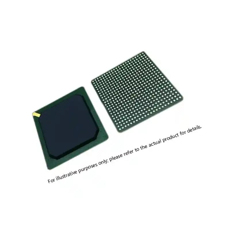
The component selection process is where DfR meets procurement, and the decisions made here set the reliability floor that no amount of testing can raise. For FPGAs, the choice between a radiation-tolerant flash-based architecture like Microsemi’s ProASIC3 or SmartFusion2, and an SRAM-based architecture with configuration scrubbing, has direct reliability implications for upset rate, reconfiguration recovery time, and total dose tolerance. I have worked with programs where selecting an A3P1000-1FGG484I over an equivalent commercial SRAM FPGA eliminated the need for an external configuration scrub controller and reduced upset-related downtime by over an order of magnitude in a tactical airborne environment.
For ADCs and DACs, specifying a part with on-chip dither and self-calibration can prevent parametric drift from being misinterpreted as a performance degradation during qualification, saving weeks of diagnostic effort. The AD9208 dual 14-bit, 3 GSPS ADC includes built-in calibration that maintains linearity across temperature, which matters when the system must meet SFDR requirements without periodic manual recalibration.
The reliability grade decision between QML-Q, QML-V, JANTX/JANTXV, or commercial with upscreening must be tied to the program’s environmental envelope, not just the contract flow-down. I have seen programs overpay for QML-V space-grade parts when a properly upscreened commercial component, with the same wafer lot traceability, additional burn-in, and 100% visual inspection, would have satisfied the MIL-STD-810 test profile and reduced lead time from 30 weeks to eight weeks. The key is documentation: the upscreening process must be documented to the same standard as a QML certificate of conformance if a DCMA audit or a source inspection is part of the contract.
| Reliability Grade | Typical Application | Upscreening Required | Documentation Level | Lead Time |
|---|---|---|---|---|
| QML-Q / Class B | Ground tactical, avionics | Per MIL-PRF-38535 | Full C of C, wafer lot traceability | 16–24 weeks |
| QML-V / Class S | Space, strategic weapons | Full MIL-PRF-38535 | DLA review, radiation lot testing | 26–40 weeks |
| JANTXV | RF, power discrete | Per MIL-PRF-19500 | C of C, source inspection | 8–16 weeks |
| Upscreened commercial | Prototyping, benign | 100% burn-in, visual, temp cycle | Custom test report, traceability chain | 6–12 weeks |
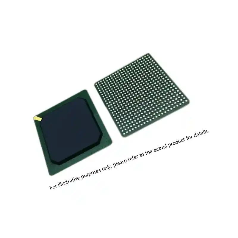
If your BOM requires specific parts like the MPF300T-FCSG536I PolarFire FPGA or the M2S150TS-FCG1152I SmartFusion2, the DfR analysis should flag whether the program’s temperature range forces an industrial-grade part, a military-grade screened version, or a custom upscreening path. Verifying actual availability before locking the BOM prevents a redesign cycle if the selected grade becomes unavailable. For programs that need an availability check on these or similar hi-rel parts, I can provide a no-obligation lead time and screening confirmation at xuansc2144@gmail.com.
Reliability Testing and Qualification
Thermal cycling and random vibration profiles per MIL-STD-810 do not simulate the service environment, they bound it. I have observed that the most useful reliability data comes from HALT (Highly Accelerated Life Testing) during the prototype phase, not from final qualification. HALT pushes the design beyond its intended limits, deliberate over-temperature, rapid thermal ramps, six-axis vibration, and combined stress, to reveal weak points that would take months to surface in a standard qualification cycle. A solder joint that fails at -55°C under 20 Grms vibration in HALT is not a pass/fail event; it is a design margin indicator that tells the team where to add underfill, change pad geometry, or select a different package. I have seen a BGA-mounted FPGA pass MIL-STD-810 vibration only to fail HALT because four corner balls were under maximum stress due to board stiffness gradient; relocating the decoupling capacitors adjacent to those balls removed the resonance and tripled the margin.
Burn-in testing for 168 hours at 125°C, following MIL-STD-883 Method 1015, catches early-life failures that wafer-level test escapes miss. For mixed-signal parts, static burn-in alone is not sufficient; applying a dynamic signal to the ADC input during burn-in can reveal oxide defects that only appear under active bias. The cost of dynamic burn-in fixtures is higher, but for a lot of 500 units going into a five-year deployment, the cost of a single field replacement including logistics, removal, and re-qualification justifies the fixture several times over.
Supply Chain Integrity
Counterfeit components remain a leading root cause of field failures in defense electronics, and the most effective countermeasure is not incoming inspection, it is source qualification before the purchase order is issued. A certificate of conformance from an unauthorized reseller is not a traceability document; it is a formality. The only traceability that holds up under a DCMA audit links the component lot code back to the wafer fab, the assembly site, and the test facility, with each transfer documented.
Working with a distributor that maintains an approved vendor list and adheres to AS6081/AS9120 quality management standards reduces the counterfeit risk at the procurement stage, long before the parts enter incoming inspection. For critical BOM lines, I recommend requiring a full provenance package: manufacturer’s certificate of origin, lot-specific test data, and packaging date codes that align with the distributor’s inventory management system. This level of transparency is what separates a transactional broker from a defense supply chain partner.
Ensuring Your Program’s DfR Starts with the Right Components
The single most effective way to reduce reliability risk in a military electronic system is to make component sourcing decisions as a deliberate part of the DfR process, not as a procurement workflow that runs in parallel. When the design team and the supply chain team share the same component risk assessment, from derating factors to lot traceability requirements, the program eliminates the information gap where most reliability problems originate. If your current design review does not include a component qualification status review gate, adding one before schematic sign-off is likely the highest-return change you can make.
For programs that need to verify source qualification, confirm lead times on mil-spec FPGAs or ADCs, or build a traceable BOM for a new design, I can provide a component availability and compliance assessment. Send the part numbers and program timeline to xuansc2144@gmail.com, and I will confirm stock status, documentation availability, and screening options within one business day. The goal is to ensure that reliability analysis translates directly into reliable parts, not into a paper exercise that assumes parts will be available in the grade and condition the design requires.
Common Questions About Military DfR
How is DfR different from reliability testing?
Reliability testing confirms whether a design meets its reliability targets after the fact. DfR is the engineering process that ensures the design inherently achieves those targets through component selection, derating, layout, and thermal management. A design that passes qualification but never underwent a formal DfR review may still pass testing by luck, but it will not have the margin to handle lot-to-lot variation or long-term degradation. I have seen a power converter pass qualification with a single lot of MOSFETs, then fail in production when a different lot with slightly higher RDS(on) pushed the junction temperature above the derating limit. DfR analysis would have flagged the inadequate thermal margin before the design was locked.
Should I always select QML-V parts for space programs?
Not necessarily. For a LEO satellite with a three-year mission life, QML-Q components with additional radiation lot testing may provide sufficient reliability at significantly lower cost and lead time. QML-V certification adds wafer lot radiation testing, extended burn-in, and full traceability to the diffusion level, which is justified for deep-space missions or strategic systems where no maintenance is possible. For many LEO and GEO payloads, I have seen programs successfully use QML-Q FPGAs with periodic configuration scrubbing and cold sparing to meet reliability requirements without the 40-week lead times that QML-V parts impose. The decision should be driven by the mission duration, radiation environment, and maintenance access, not by a blanket specification.
Can upscreened commercial components match military-grade reliability?
In some cases, yes, but only when the upscreening process is defined with the same rigor as a QML qualification. A commercial FPGA that undergoes 100% burn-in, temperature cycling, and visual inspection per MIL-STD-883 can achieve reliability comparable to a hermetically sealed military-grade part for ground-based and airborne applications where the environment does not require hermeticity. The critical distinction is that the upscreening must be performed by a qualified test house with a documented process, and the traceability chain must remain intact from wafer lot to final test. I have seen upscreened commercial ADCs perform without a single field failure in an airborne SIGINT system that operated from -40°C to 70°C, but the program invested in a lot-specific reliability report that matched the content of a QML C of C. Without that documentation, the reliability proof is only anecdotal.
How do I manage DfR for a program with obsolescent components?
Obsolescence is a reliability problem in slow motion. When a component goes end-of-life, the replacement part may have different electrical characteristics, package dimensions, or radiation performance, and a simple form/fit/function replacement often introduces new failure modes. A DfR process should include a technology refresh plan that identifies at-risk components and evaluates alternate sources with derated parameters in parallel to the primary design. I recommend maintaining a die bank for FPGAs and custom ASICs that have no second source, because wafer availability for older process nodes disappears faster than distributors can stock finished units. For standard logic, memory, and interface ICs, working with a distributor that can provide second-source options from multiple approved manufacturers extends the program’s sourcing flexibility well beyond the last-time-buy window. If your program needs an obsolescence review for a BOM that includes end-of-life mil-spec parts, send the part list to xuansc2144@gmail.com and I will provide a drop-in replacement assessment or a die-banking recommendation.
If you’re interested, check out these related articles:
A1020B-PG84B ACT2 FPGA: Specs, Sourcing, and Availability
XC7VX485T Virtex-7 FPGA: Performance and Sourcing for Defense
Virtex-7 690T FPGA: Performance, Packaging, and Reliability Insights
Virtex-7 XC7VX690T: Performance and Reliability Insights
XCKU115 UltraScale FPGA: Powering Critical Defense Systems