VI-26L-IU Maxi DC-DC Converter: 24-375 V Input, IU Package
Table of Contents
- How to Read the VI-26L-IU Rating Before Design-In
- Matching the 24-375 V Input Window to the Real Bus
- IU Package Thermal and Mechanical Integration
- Output Rail, Protection, and Load Interaction
- Sourcing and Verification for High-Rel Programs
- Next Step: Confirm VI-26L-IU Availability and Documentation
- FAQ
- Does the VI-26L-IU output a fixed voltage?
- Can the converter be used on a 270 V or 375 V bus without an input limiter?
- What documentation should a defense buyer expect?
- Does the IU package require forced air?
The VI-26L-IU is a Maxi DC-DC converter module listed with a 24-375 V input window and an IU package. For high-reliability and defense power designers, the most useful way to approach this part is as a conditioned power building block, not as a universal rail generator. The decision that matters first is whether the complete part number, output setting, thermal grade, package configuration and source documentation match the actual bus transient environment and the load regulation budget. When that match is verified, the VI-26L-IU can support an intermediate bus, a point-of-load group, or a replacement in a legacy power stage. When it is not verified, even a wide input rating can hide startup, transient or thermal failure.
How to Read the VI-26L-IU Rating Before Design-In
The listing identifies the input window and package, but it does not by itself define the output rail or the full electrical rating. A responsible design review starts with the complete part number and dash suffix, then checks the exact input voltage range, output voltage, output current, temperature grade and package pinout. Different Maxi DC-DC modules can share a similar form factor while having different input and output characteristics, so a same-series substitution is not automatically valid.
The 24-375 V input range should be treated as a system compatibility requirement, not as a one-line approval for every bus. A wide input window helps when the source varies across operating conditions, but the converter may still require external filtering, transient limiting or input capacitance when the real bus exceeds its continuous rating during surges, load dumps or engine cranking. The first engineering deliverable is therefore a bus profile, not just a part number.
Matching the 24-375 V Input Window to the Real Bus
A converter built for a wide DC input still depends on the surrounding power source. For aircraft applications, MIL-STD-704F defines normal and transient limits for power quality, including 28 VDC and 270 VDC conditions [1]. For military ground vehicles, MIL-STD-1275E defines 28 VDC transients including surges, spikes, cranking drops and load dump conditions [2]. These documents help the designer decide whether the converter alone can accept the available bus, or whether an input filter, limiter or hold-up stage must precede it.
Before committing the VI-26L-IU, the responsible check is to compare the actual bus envelope with the module input specification under all expected conditions. Minimum input voltage during brownout or battery discharge must be above the converter undervoltage lockout point. Maximum transient voltage must not exceed the allowed input rating. Start-up behavior at low line and full load must be confirmed because a wide input rating does not guarantee full power at every point in the stated window.
| Verification point | What to confirm | Engineering impact |
|---|---|---|
| Complete part number | Input, output, package, grade and dash suffix | Avoids substituting a same-series part with different input or output. |
| Input range and transients | 24-375 V window plus surge, dropout and spike limits | Determines whether the converter survives bus transients without external clamping. |
| Output rail and regulation | Voltage, current, line/load regulation and ripple | Confirms the output actually meets the load tolerance. |
| Thermal package and derating | IU package mounting, baseplate temperature and airflow | Sets the usable current margin at worst-case ambient. |
| Protection features | Overcurrent, overvoltage, overtemperature and remote sense | Defines fault behavior and control integration. |
| Documentation | C of C, traceability, test data and counterfeit mitigation | Supports source acceptance for high-reliability programs. |
IU Package Thermal and Mechanical Integration
The IU package determines the mechanical interface, baseplate and mounting approach. For defense boards, mechanical fit is not enough. The thermal path from the converter baseplate to the chassis or heatsink sets the actual available output current at elevated ambient. A module may be rated at a nominal case temperature, but usable power can be lower when airflow is restricted or adjacent components raise the local board temperature.
The proper check is to compare the application worst-case ambient, the converter derating curve and the baseplate temperature limit. Package outline, pin spacing and mounting hardware must also match the intended printed circuit board or chassis arrangement. A mechanically compatible package that is operated outside its thermal envelope will still fail prematurely, regardless of the electrical rating.
Output Rail, Protection, and Load Interaction
The output voltage is defined by the complete converter configuration, not by the VI-26L-IU abbreviation alone. The design must also account for line regulation, load regulation, output ripple, remote sensing and protection behavior. Overcurrent, overvoltage and overtemperature functions should be understood before layout because they determine how the converter behaves during a load fault or a cooling failure.
Many boards using a Maxi converter feed point-of-load regulators for FPGAs, DSPs and memory. Representative hi-rel loads often sourced alongside this class of converter include the Microsemi SmartFusion2 M2S150-FCVG484I, a mixed-signal FPGA with multiple rails 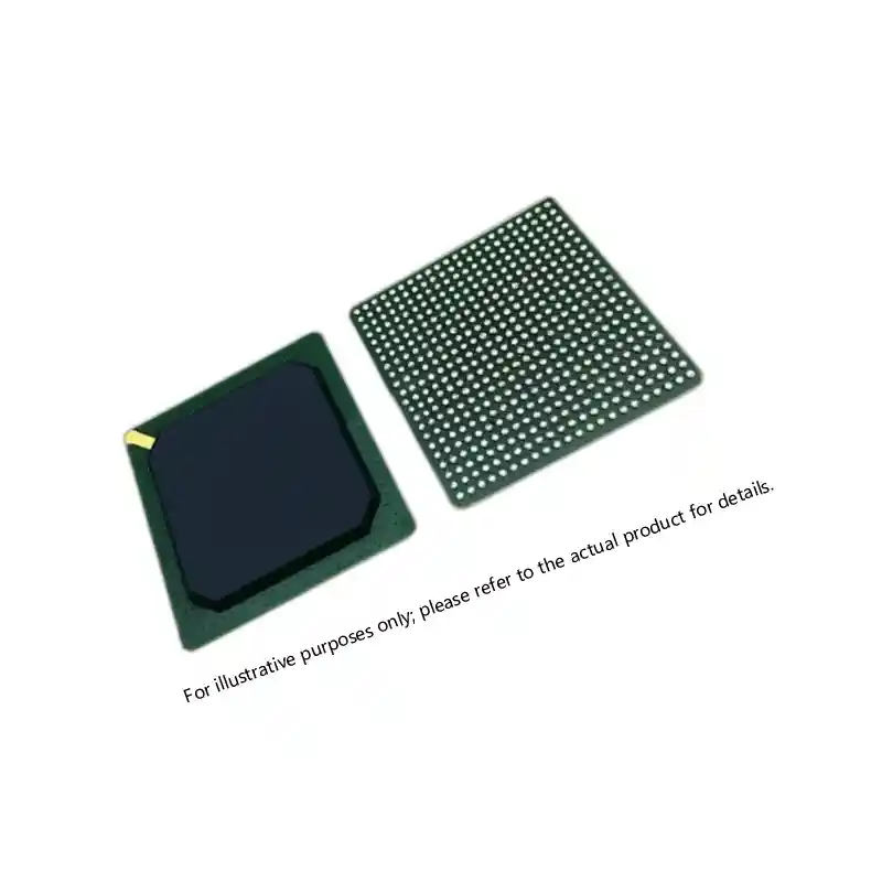 ; the Actel A54SX72A-CQ208B antifuse FPGA, where simple core current still requires a stable monotonic rail
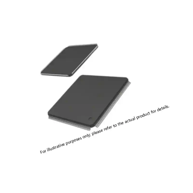 ; the Actel AX1000-1CQ352M Axcelerator FPGA, which has tighter inrush and decoupling demands
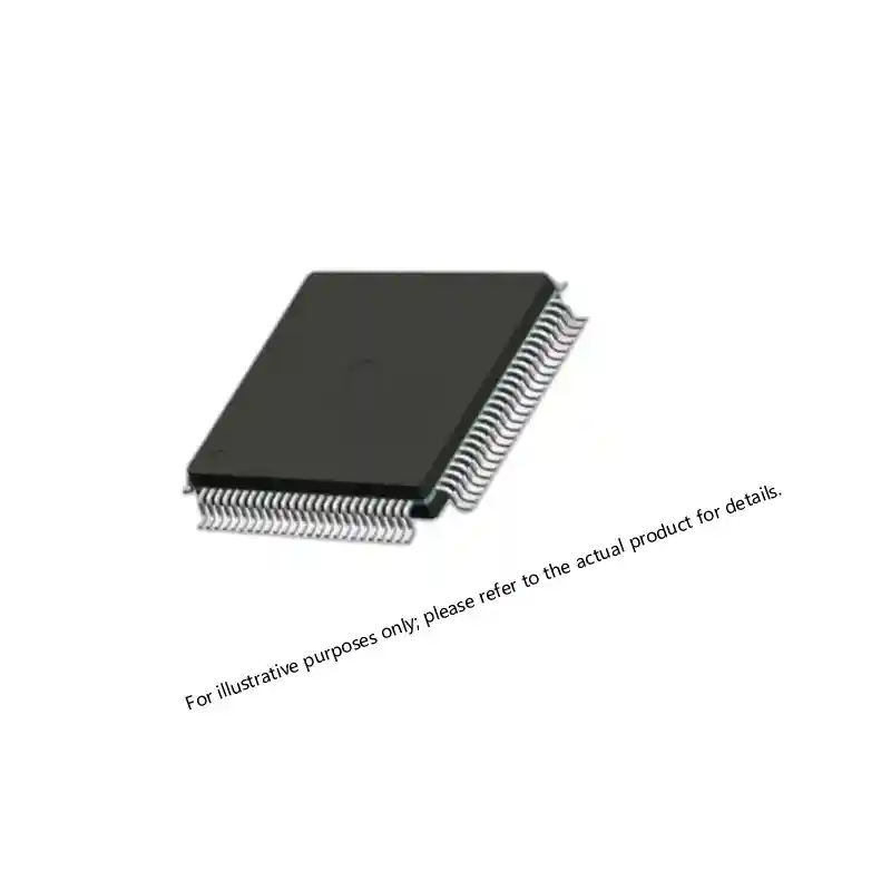 ; the Actel A3P1000-FGG484I ProASIC3 device used in lower power but long lifetime programs
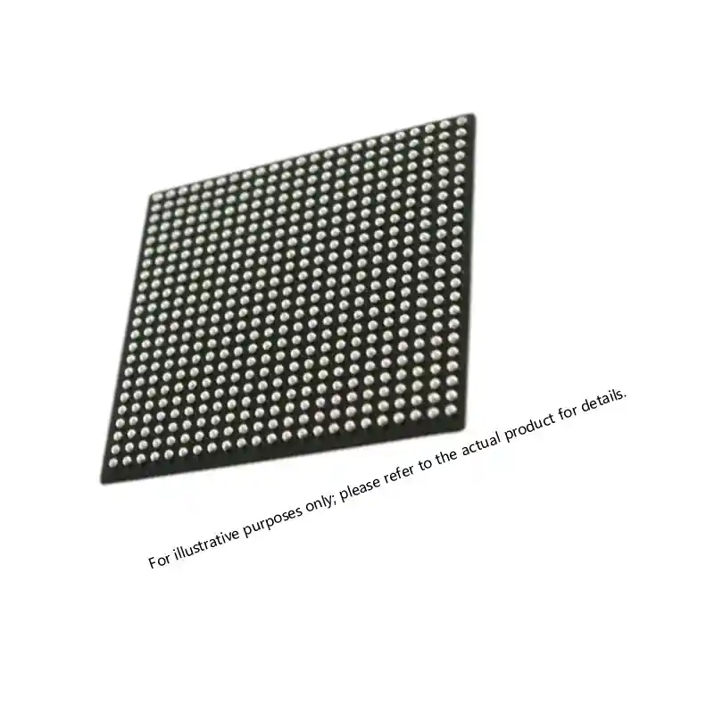 ; and the Microsemi SmartFusion2 M2S150TS-FCG1152I variant in larger package pinouts
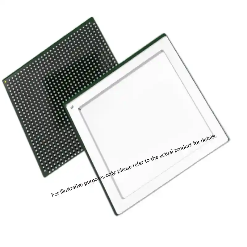 . Each load has different rail sequencing and noise sensitivity, so the converter selection cannot stop at output voltage.
FPGA rail planning is part of the same design decision. <XCKU085 UltraScale FPGA: Performance for Critical Systems> covers selection for critical systems where the power architecture must support high-performance processing without sacrificing source control.
Sourcing and Verification for High-Rel Programs
For military and high-reliability programs, the component alone is rarely sufficient for source acceptance. Buyers should request a certificate of conformance, traceability records from the manufacturer to shipment, available test data and evidence of counterfeit risk controls consistent with SAE AS5553 [3]. The procurement record should also identify the complete part number and any required screening or qualification markings.
The same source-control discipline that protects the power module should apply to the FPGAs, memory and analog devices that the converter supplies. A complete bill of materials with traceable part numbers, lot information and documentation is easier to audit than a mixed list assembled from multiple uncontrolled sources. For long-running defense programs, this documentation trail is often more important than unit cost alone.
Next Step: Confirm VI-26L-IU Availability and Documentation
Send the complete part number, required output voltage, input transient profile, temperature range and source documentation baseline to xuansc2144@gmail.com. Sparkle Electronics can check availability, traceability and configuration fit before the power stage is locked into the design.
FAQ
Does the VI-26L-IU output a fixed voltage?
The output is determined by the complete part number and dash code, not by the VI-26L-IU abbreviation alone. The listing identifies the input window and package, so the exact output rail and current rating must be confirmed from the full part number and application data.
Can the converter be used on a 270 V or 375 V bus without an input limiter?
It depends on the bus transients and the module continuous input rating. A wide input rating helps with steady-state variations, but MIL-STD-704 or MIL-STD-1275 transients can still exceed the rating and require filtering or limiting before the converter.
What documentation should a defense buyer expect?
The buyer should expect a certificate of conformance, traceability from manufacturer to shipment, available test data and counterfeit mitigation records consistent with SAE AS5553. The documentation should match the exact part number and lot information.
Does the IU package require forced air?
The thermal requirement depends on load, ambient temperature and baseplate mounting. The package alone does not guarantee full power. The converter must be used within its derating curve and the application worst-case thermal environment.
References
[1] MIL-STD-704F, “Aircraft Electric Power Characteristics,” U.S. Department of Defense, 2004.
[2] MIL-STD-1275E, “Characteristics of 28 Volt DC Electrical Systems in Military Vehicles,” U.S. Department of Defense, 2013.
[3] SAE AS5553C, “Counterfeit Electrical, Electronic, and Electromechanical (EEE) Parts; Avoidance, Detection, Mitigation, and Disposition,” SAE International, 2022.
If you’re interested, check out these related articles:
Virtex-7 690T FPGA: Performance, Packaging, and Reliability Insights
Virtex-7 690T FPGA: Performance for Mission-Critical Systems
A1020B-PG84B ACT2 FPGA: Specs, Sourcing, and Availability
UltraScale KU085 FPGA Specifications for Defense Systems
Virtex-7 XC7VX690T: Performance and Reliability Insights