Space Vacuum Electronics: Reliability in Vacuum and Radiation
Table of Contents
- What Space Vacuum Does to Electronic Components
- Radiation Effects on Space Electronics
- Qualification Standards for Space-Grade Components
- Selecting Components for Long-Term Reliability in Space
- Sourcing Space-Grade Components: What Procurement Engineers Need to Know
- Best Practices for Ensuring Electronic Reliability in Space Missions
- Common Questions About Space Vacuum Electronics
- What is the difference between radiation-hardened and radiation-tolerant components?
- How do I know if a component is vacuum compatible?
- Can I use COTS components in space applications?
- What documentation should I request when procuring space-grade components?
Space vacuum electronics face reliability challenges that go well beyond the radiation effects most engineering guides cover. In a vacuum, materials outgas, thermal dissipation relies solely on conduction, and radiation-induced single-event effects can corrupt data without warning. I have spent over a decade supporting defense and aerospace programs with component selection, and I consistently see design teams underestimate the combined stress of vacuum and radiation on packaging, interconnects, and passive components. This article examines the failure mechanisms, qualification standards, and sourcing practices that determine whether electronic components survive in space environments — and how procurement decisions made early in a program directly affect mission reliability.
What Space Vacuum Does to Electronic Components
In a vacuum, there is no convective cooling. Heat must be removed by conduction through the PCB and chassis, which puts higher demands on junction temperature management and requires careful derating. A more subtle threat is outgassing. Organic materials in packaging materials, adhesives, and conformal coatings release volatile compounds under low pressure. These can condense on optical surfaces, contaminate contacts, or create conductive paths that degrade insulation resistance.
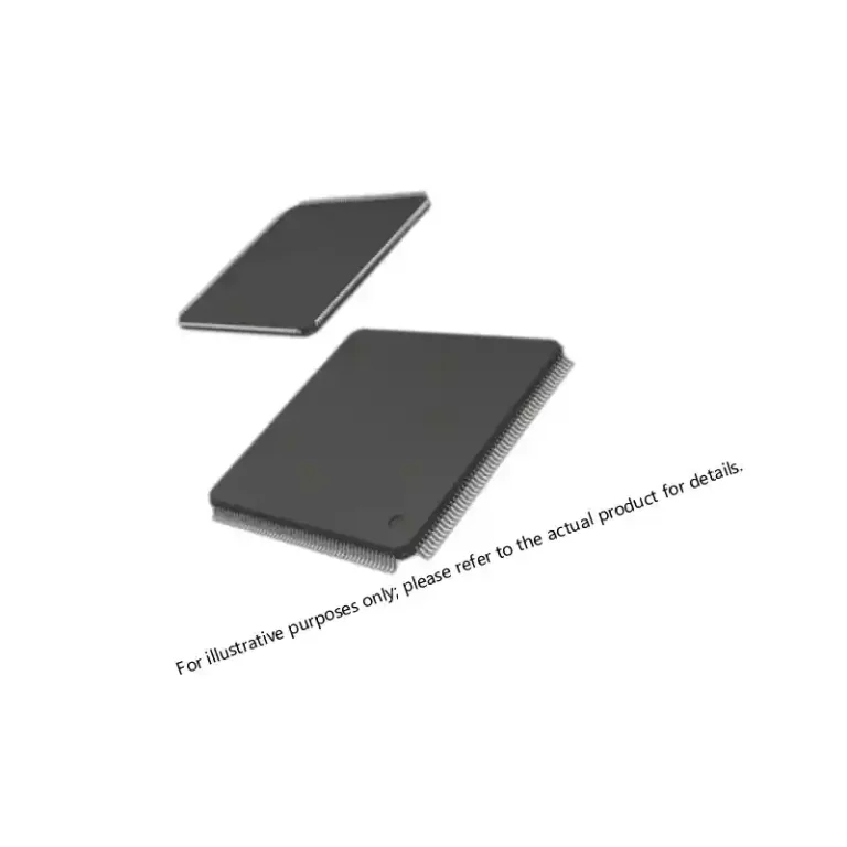
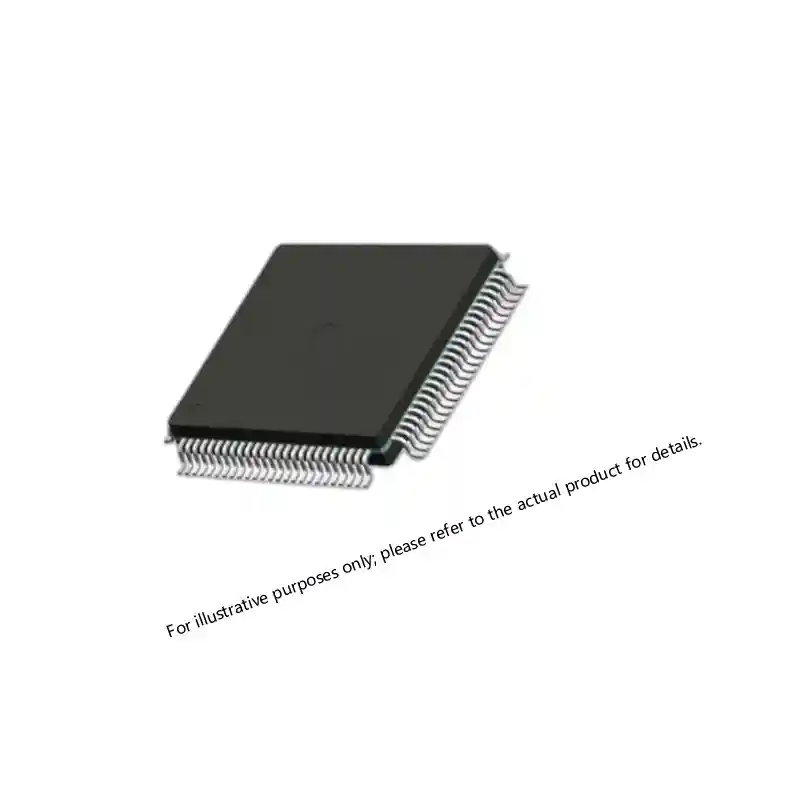
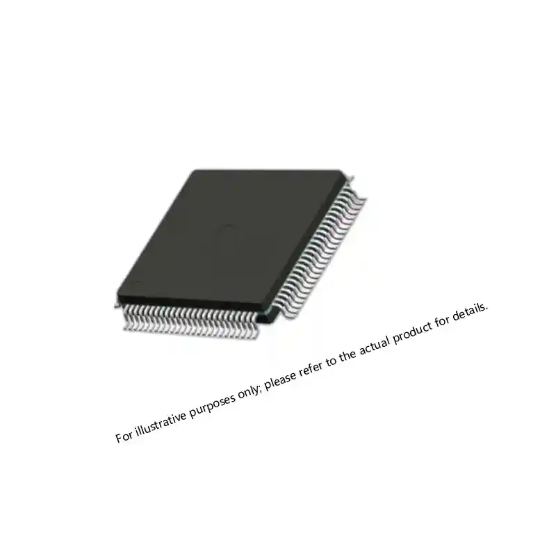
Plastic-encapsulated microcircuits (PEMs) are particularly vulnerable. Most commercial PEMs use mold compounds that exhibit significant outgassing above 125°C. I have seen programs where designers selected plastic QFP packages for a LEO satellite, only to have the qualification campaign halted when board-level RGA (residual gas analysis) test results showed contamination exceeding program limits. Ceramic packages with gold-plated leads avoid this problem entirely. Materials like Kovar lids and alumina substrates have decades of flight heritage and extremely low total mass loss (TML) and collected volatile condensable material (CVCM) measured per ASTM E595.
The loss of air dielectric also changes voltage standoff behavior. Spacings that are safe at sea level can break down in vacuum at much lower voltages because Paschen’s law shifts the minimum breakdown potential. That means the design rules that worked for a ground-based system do not automatically transfer to orbit. Component manufacturers sometimes provide vacuum-specific maximum voltage ratings, and those data points should be requested during the qualification review.
Radiation Effects on Space Electronics
Radiation in space comes from trapped particles in the Van Allen belts, solar particle events, and galactic cosmic rays. For electronic components, the main effects are total ionizing dose (TID), displacement damage, and single-event effects (SEE).
TID accumulates over time and shifts transistor threshold voltages. CMOS devices in particular suffer increased leakage current as the gate oxide traps charges. A part rated for 100 krad(Si) may remain functional, but its analog performance — input offset voltage, gain-bandwidth product, supply current — can drift far outside spec long before a functional failure occurs. That is a nuance that a datasheet TID rating alone does not capture.
Single-event latchup (SEL) is a different animal. A single heavy ion can trigger a parasitic silicon-controlled rectifier (SCR) structure, shorting power to ground and potentially destroying the device before any telemetry flag trips. Antifuse FPGAs — such as the Microsemi Axcelerator family — are immune to SEL by construction because they have no configuration SRAM cells. I have specified the AX1000-CQ352M for multiple high-reliability payloads precisely for this reason. For SRAM-based FPGAs, mitigation typically requires triple-module redundancy (TMR) and configuration scrubbing, which add power and complexity.
Displacement damage degrades bipolar transistors and optocouplers by knocking atoms out of the crystal lattice, reducing minority carrier lifetime. This shows up as degraded current gain (hFE) and increased forward voltage. GaAs and wide-bandgap semiconductors are inherently more resistant, but they still need to be characterized at the expected mission fluence.
Qualification Standards for Space-Grade Components
No single standard governs all space-grade components, but the most commonly referenced are MIL-PRF-19500 (discrete semiconductors), MIL-PRF-38534 (hybrid microcircuits), and MIL-PRF-38535 (monolithic ICs) for military-grade devices. For space-specific requirements, NASA EEE-INST-002 and ESA ECSS-Q-ST-60-14-02C provide detailed part selection and derating guidelines.
The following table summarizes typical qualification tests and their purposes:
| Test | Standard Reference | What It Verifies |
|---|---|---|
| Thermal vacuum cycling | MIL-STD-883 TM 1010 | Outgassing, mechanical integrity under temperature extremes in vacuum |
| Mechanical shock & vibration | MIL-STD-202 TM 213, 214 | Survival during launch and deployment |
| Total ionizing dose (TID) | MIL-STD-750 TM 1019 | Cumulative radiation hardness up to specified krad(Si) |
| Single event effects (SEE) | EIA/JEDEC JESD57 | Latchup, upset, and burnout immunity at specific LET thresholds |
| Outgassing (TML/CVCM) | ASTM E595 | Acceptable mass loss and condensable volatiles for vacuum use |
Every lot of components destined for a space application should have traceable paperwork showing these tests were performed. A manufacturer’s certificate of conformance alone is not a substitute for lot-specific radiation and outgassing data. In programs I support, we require suppliers to provide raw test reports, not just summaries, so we can verify the test conditions match the actual mission environment.
Selecting Components for Long-Term Reliability in Space
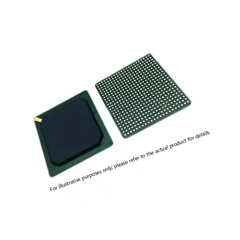
Packaging is the first filter. Ceramic packages (CQFP, CGBA, CLCC) with gold-plated leads or nickel-palladium finishes are the default choice for vacuum-compatible, long-life missions. Kovar lids and sealed cavities ensure moisture and contaminant levels remain below 0.5% internal water vapor content per MIL-STD-883 TM 1018. For memory and FPGA devices, hermetic BGA and column grid array packages exist, but they are more limited in pin count and speed grade than their non-hermetic commercial counterparts.
At this stage, procurement engineers need to align BOM items with the right radiation hardness classification. Three broad tiers exist:
- Radiation-hardened (rad-hard): verified to at least 100 krad(Si) TID and typically latchup-immune to LET > 80 MeV-cm²/mg. Devices such as the Actel AX2000-CQ256M or the A54SX72A fall here.
- Radiation-tolerant: may survive 30-50 krad(Si) and exhibit lower SEE cross-section, but not latchup-immune. Often derived from industrial-temperature versions of commercial ICs with enhanced screening.
- Commercial off-the-shelf (COTS) up-screened: selected and tested for radiation effects on a lot-by-lot basis. Costs less but carries higher risk of lot-to-lot variation.
I have found that satellite programs with a three-year design life often try to save money by using COTS parts with up-screening. That can work — provided the screening plan is tailored to the specific orbit and shielding. But if the mission has a service-level agreement for a ten-year lifetime, the qualification effort and re-screening costs frequently erase any upfront savings.
Midway through component selection, it is worth confirming that the distributor can provide lot-specific radiation test reports for the exact date codes being quoted. If your program involves a polar orbit with elevated proton flux, ask for displacement damage test data on any bipolar or optocoupler part numbers before locking in the BOM. A quick review with a technical sourcing team can catch specification gaps early. Reach out at xuansc2144@gmail.com with your part list and we’ll check the available qualification data.
Sourcing Space-Grade Components: What Procurement Engineers Need to Know
The supply base for space-grade semiconductors is small. Wafer fabrication and packaging must occur at certified facilities — often QML-qualified lines — and production runs happen infrequently. That generates two persistent pain points: long lead times and allocation-driven shortages. I recall a program that waited 42 weeks for a specific rad-hard FPGA because the manufacturer had allocated that quarter’s entire wafer output to a prime contractor.
Independent distributors who specialize in hi-rel components can mitigate that risk by holding inventory of long-lead items. They also play a role in verifying authenticity. Counterfeits are rare in the space-grade market compared to commercial electronics, but when they appear they are dangerous. A distributor should be able to show a full chain of custody from the original component manufacturer, including lot codes, date codes, and copies of original qualification records. AS6081 certification is a reliable indicator that an independent distributor has robust counterfeit detection processes. I recommend asking any potential source whether they perform incoming visual inspection per MIL-STD-883 TM 2009, X-ray inspection, and decapsulation spot checks on material not coming directly from the OCM.
Best Practices for Ensuring Electronic Reliability in Space Missions
Successful programs treat component selection as a system-level risk decision, not a procurement afterthought. Start qualification early. Derate according to the mission’s radiation design margin (RDM), not the datasheet absolute maximums. Build a worst-case circuit analysis (WCCA) that accounts for end-of-life parameter shifts from TID and temperature cycling. And maintain a bridge buy of critical components to cover schedule slip — six months of inventory is cheap compared to a mission delay.
Working with a distributor who understands both the technical and compliance sides of space procurement changes the risk equation. They can cross-reference alternative part numbers from multiple manufacturers, verify that the packaging and lead finish meet outgassing and tin whisker requirements, and assemble the documentation package your reviewers expect. That level of support is what turns a transactional quote into a program partnership.
If your next satellite build requires components verified for vacuum and radiation environments, send your part numbers and quantities to xuansc2144@gmail.com. We’ll confirm stock availability, pull lot-specific qualification data, and provide a compliance-ready quote so your team can focus on the design review instead of chasing test reports.
Common Questions About Space Vacuum Electronics
What is the difference between radiation-hardened and radiation-tolerant components?
Radiation-hardened parts are designed and tested to survive total ionizing dose levels of at least 100 krad(Si) and are latchup-immune up to high LET thresholds, typically above 80 MeV-cm²/mg. Their fabrication process, layout, and package are all built around radiation survival. Radiation-tolerant components are not hardened by design but have been characterized at lower dose levels — commonly 30 to 50 krad(Si) — and may still experience soft errors or parametric drift beyond that. For a GEO comsat, radiation-hardened parts are near-mandatory. For an experimental LEO CubeSat, tolerant parts with adequate shielding can be acceptable.
How do I know if a component is vacuum compatible?
Review the manufacturer’s outgassing test data per ASTM E595. Acceptable limits are typically TML ≤ 1.0% and CVCM ≤ 0.1%. Beyond the numbers, check the package material: ceramic packages with gold-plated leads and hermetically sealed lids are inherently vacuum-compatible. Plastic-molded packages, elastomeric seals, and tin-plated terminations are red flags — tin whiskers can grow in vacuum and cause shorts, and most mold compounds exceed CVCM limits during thermal cycling. Always request the test data for the exact lot you intend to buy.
Can I use COTS components in space applications?
Yes, but only after a rigorous up-screening process that includes burn-in, temperature cycling, and radiation characterization of multiple samples from each lot. Many small satellite programs follow this path to keep costs down. The downside is lot-to-lot variability: a COTS microcontroller that passed 50 krad(Si) in one lot may fail at 30 krad(Si) in the next because the fab process drifted. For missions with limited redundancy or long design lives, the recurring screening costs often justify moving to a QML-V or radiation-hardened part instead.
What documentation should I request when procuring space-grade components?
At minimum, you need a certificate of conformance (CoC) that traces each part to its original manufacturer, along with lot-specific test reports for the qualification tests that matter to your mission: TID test data, SEE test reports, outgassing results, and any additional screening such as PIND (particle impact noise detection) for cavity packages. Ask for the full test report, not just a summary, so you can verify that test conditions — dose rate, temperature, bias — match your orbital environment. Having this documentation package ready before your PDR can compress your qualification timeline significantly. If you are unsure whether the reports you currently receive meet your program’s requirements, sharing your specification sheet with a specialized distributor is a practical way to close documentation gaps. Send your requirements to xuansc2144@gmail.com and we’ll confirm what compliance data is available for each line item.
If you’re interested, check out these related articles:
Virtex-7 690T FPGA: Performance for Mission-Critical Systems
XCKU115 UltraScale FPGA: Powering Critical Defense Systems
UltraScale KU085 FPGA Specifications for Defense Systems
XCKU085 UltraScale FPGA: Performance for Critical Systems